22
MAINTENANCE & CLEANING
REMOVAL INSTRUCTIONS
OVEN CONTINUED
Elements
Remove oven racks and right hand rack slide from oven. Remove the wing nuts holding oven
baffle to right hand of oven. Remove oven baffle from oven. Remove 4 screws holding oven
elements to right hand of oven. Gently pull elements away from right hand of oven. Noting
wire locations, disconnect wires from element. Discard old element. Reverse removal
instructions to assemble.
RANGE TOP
Thermostat
Secure range top from power. Open front control panel and feed capillary tube up towards grill
plate. Using two 9” braces, lift the griddle plate up and secure with the two 9” braces. Remove
capillary tube holders from the center of the element pan assembly and gently remove from
griddle area. Remove two sheet metal screws holding control panel to range top and remove
control panel. Remove the thermostat knob and two screws holding the thermostat to the
control panel. Discard old thermostat. Reverse removal instructions to install new thermostat.
Elements
Secure range top from power. Using two 9” braces, lift the griddle plate up and secure with the
two 9” braces. Remove capillary tube holders from the center of the element pan assembly and
gently remove from griddle area. Remove wires from element terminals, noting the wire
locations. Remove the five nuts holding the element pan assembly to the bottom of the griddle.
Remove defective element from the element pan and discard defective element. To install
reverse removal instructions.
6-Heat Switch
Secure range top from power. Remove two sheet metal screws holding control panel to range
top and remove control panel. Remove the 6-heat switch knob and two screws holding the 6-
heat switch to the control panel. Remove wires from the 6-heat switch terminals noting the wire
locations. Discard old 6-heat switch. Reverse removal instructions.
French Plate
Secure range top from power. Using two 9” braces, lift the French plate frame assembly up and
secure with the two 9” braces. Remove wires from the element terminals, noting the wire
locations. Remove defective French plate assembly from the range. To install reverse removal
instructions.
Summary of Contents for 9P-RT36D-440VG
Page 4: ...4 CHANGE RECORD Change no Date Title and or Brief Description Signature of Validating Officer...
Page 11: ...11 SPECIFICATION SHEET...
Page 12: ...12 SPECIFICATION SHEET...
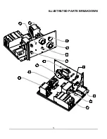
Page 23: ...23 ILLUSTRATED PART BREAKDOWN...
Page 24: ...24 ILLUSTRATED PARTS BREAKDOWN...
Page 25: ...25 ILLUSTRATED PARTS BREAKDOWN...
Page 26: ...26 ILLUSTRATED PARTS BREAKDOWN 34...
Page 27: ...27 ILLUSTRATED PARTS BREAKDOWN...
Page 28: ...28 ILLUSTRATED PARTS BREAKDOWN...
Page 30: ...30 WIRING DIAGRAM...


