7
INSTALLATION INFORMATION
THE INSTALLATION INSTRUCTIONS CONTAINED HEREIN ARE FOR THE USE OF
QUALIFIED INSTALLATION AND SERVICE PERSONNEL ONLY. INSTALLATION OR
SERVICE BY OTHER THAN QUALIFIED PERSONNEL MAY RESULT IN DAMAGE TO THE
OVEN AND/OR INJURY TO THE OPERATOR.
Quali
fi
ed installation personnel are individuals, a
fi
rm, a corporation, or a company which either
in person or through a representative are engaged in and responsible for:
1. The installation or replacement of gas piping and the connection, installation, repair, or
servicing of equipment.
2. The installation of electrical wiring from the electric meter, main control box, or service outlet
to the electric appliance.
Quali
fi
ed installation personnel must be experienced in such work, familiar with all precautions
required, and have complied with all requirements of state or local authorities having
jurisdiction.
LOCATION
The well-planned and proper placement of your oven will result in long-term operator convenience
and satisfactory performance.
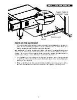
NOTE:
On gas conveyor ovens, routine servicing can usually be accomplished within the limited
movement provided by the gas hose restraint. If the oven needs to be moved further from the
wall, the gas must
fi
rst be turned off and disconnected from the oven before removing the restraint.
Reconnect the restraint after the oven has been returned to its regular position.
It is essential that an adequate air supply to the oven be maintained to provide a suf
fi
cient
fl
ow
of combustion and ventilation air. Follow these guidelines:
1. Place the oven in an area that is free of drafts.
2. Keep the oven area free and clear of all combustibles such as paper, cardboard,
fl
ammable
liquids, and solvents. Oven should only be used on Non-Combustible Floors.
3. Do not place the oven on a curb base or seal to a wall. This will restrict the
fl
ow of air and
prevent proper ventilation to the blower motors. This condition must be corrected to prevent
permanent damage to the oven.
4. On all models, tripping of the blower motor's thermal overload device indicates an excessive
ambient temperature at the back of the oven. This condition must be corrected to avoid
permanent damage to the oven.
GAS SUPPLY RATING AND SIZING
Calculations for pipe sizing must take into account the maximum usage rate of all other appliances
in the kitchen or one or more of the appliances will suffer from inadequate or dangerous
performance. The 3/4" NPT connection for the oven is generously sized for use in the control
box of the oven. However, unless the oven installation is within 10 feet of the main building gas
supply, the supply must be larger. For each oven, a 3/4" NPT
fl
exible quick connect hose and
full port gas shut-off valve is recommended as a MINIMUM. The main pipe supplying each oven
branch may need to be larger depending on the number of appliances serviced, the number
of elbows in the piping, and the pressure. This should be sized and installed by a professional
familiar with any local codes that may also affect the installation.
ACCESS CONSIDERATIONS
Locating the gas valve(s), quick connect hose(s) and electrical outlet(s) at the control box end
of the oven will allow easier access for any service visits. This improved access should make
any necessary service quicker resulting in less kitchen disruption. It will also allow easier
disconnection of electricity, gas, and restraints for cleaning around and behind the oven.
UTILITY INSTALLATION
Summary of Contents for Ultra-max UM3240
Page 27: ......


