background image

10

10. Troubleshooting

When trouble is found, check the following again before consulting your dealer. If none of these is applicable or the the 

trouble is not remedied even after action has been taken, a failure of this product is suspected.

 Check/Remedy

Cause

Solution

Pilot Lamp does not light.

Power Switch is OFF.

Turn ON the switch.

AC Adapter is not connected correctly. 

Check the connection. 

Internal Fuse is blown

Contact your dealer.

Motor does not run

Tubing, Motor Cord, AC Adapter is not connected 

correctly. 

Check the connection.

Air pressure is not given, or not at proper level from the 

delivery unit.

Check the air pressure of the delivery system.

Check the ERROR CODE in the Speed Indicator.

Refer to 9. ERROR CODE.

The rotation speed does not rise. 

Air pressure is not given, or not at proper level from the 

delivery unit.

Check the air pressure of the delivery system.

Air pressure of the delivery unit is lower than the “Lower 

limit of the air pressure”.

Do "6. (1) Foot Air Calibration". 

It beeps when switch is turned 

on.

You are stepping on the Foot Pedal when turning on the 
power switch. (Safety function)

Do not press the Foot Pedal, and turn on the 

power switch simultaneously.

Light Bulb does not light.

Light Bulb is not connected correctly.

Insert the Light Bulb correctly and firmly. (Refer 

to 8. (2) Replacing Bulb)

Light Bulb is burnt-out

Please replace the Bulb. (Refer to 8. (2) 

Replacing Bulb)

Motor heats up abnormally 

during operation.

Coolant air is not given, or not at proper level from the 

delivery unit. 

Check the air pressure of the delivery system.

Water leakage

Tubing, Motor Cord is not connected correctly.

Check the connection.

If leak is from Control Box, something is wrong within the 

Control Box. 

Contact your dealer.

When turned on, the setting 

values are different from what 

used to be when turned off.

Turned off the motor while rotating.

Turn off after the Motor has stopped.

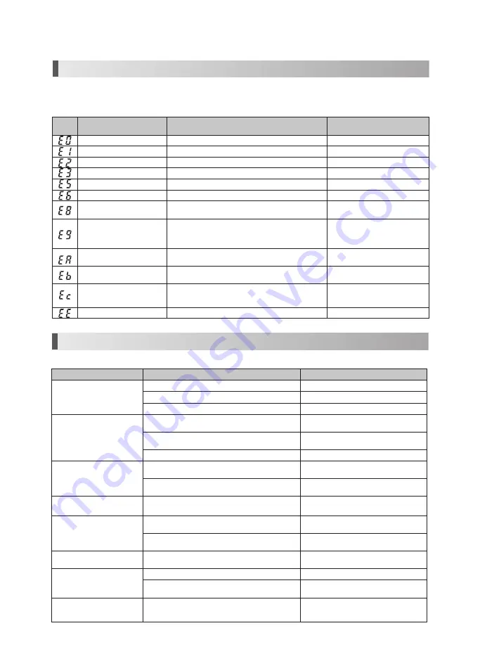
9. 

Error Code

Error 

Code

Trouble

Cause

Check/Remedy

Overcurrent error. (In circuit)

Detected overcurrent in the circuit. 

Contact your dealer.

Overcurrent error. (In software) Detected overcurrent in the software.

Contact your dealer.

Retry Error

Motor stopped by overload, and not able to restart. 

Contact your dealer.

ITRIP Error

Faulty Motor or Internal circuit. 

Contact your dealer.

Overvoltage Input Error

Overvoltage is given to the Control Box. 

Contact your dealer.

Bulb voltage Error

Overvoltage is given (more than 3.7V) from the Internal circuit.  Contact your dealer.

Overheat Error 

High temperature safe system is functioning, due to long-

time use at a high load.

Allow unit to cool and try again. 

Motor Start Error

- Motor didn't reach the preset speed in a prescribed 

period of time. 

- Break down of a motor cord wire, or internal circuit 

malfunction. 

Contact your dealer.

Bulb voltage Error

Voltage for the Bulb did not reach the preset level in a 

prescribed period of time. 

Contact your dealer.

Air Offset Error

Lower than preset " Lower limit of the air pressure"

Displayed by Foot Air Calibration 

function. Not a malfunction.

Air Full Scale Error

- Higher than preset "Upper limit of the air pressure".

- Air pressure higher than 0.4MPa (=4.0kgf/cm

2

=56.89psi) 

is given.

Displayed by Foot Air Calibration 

function. Not a malfunction.

EEPROM Error

Malfunction of the memory for the setting values.

Contact your dealer.

If the motor stops due to an abnormality such as a malfunction, overload, breakage or incorrect usage, the Control Box will 

display an error code on the Speed Indicator. If an error code is displayed, turn on the power again and check whether the 

same error code is displayed. If the same error code is displayed, take action by referring to the instructions provided in 

the "Check/Remedy" column in the following table.

Summary of Contents for NuTorque Lite

Page 1: ...plains an instruction that should be observed for safety reasons Read this manual thoroughly before use and operate the device properly These instructions will show you how to operate the product safety and prevent danger to you or others They are classified by the degree and or severity of danger All contents relating to safety should be oberserved Cautions for handling and operation Please Read ...

Page 2: ...the Speed Control Switch is adjusted within the allowable speed before use When you install Control Box or Motor DO NOT bend or twist the tubing or the cord No unnatural force is needed to do the installation Never use the AC adapter for anything other than the control box of this product Air Requirements dry free from contamination and oil Use a compressor with a dry air system Install an air fil...

Page 3: ...Model 265290 120V and 265291 230V Rated input AC120V 50 60Hz 41VA AC230V 50 60Hz 41VA Output AC28V 1 3A Fuse AC120V FU100 T1 6A 250V FU101 T1 6A 250V AC230V FU100 T800mA 250V FU101 T800mA 250V Dimensions W100 x D178 x H64 mm Cord Length Unshielded App 5 0m AC Adaptor Handpiece Tubing Connector Handpiece Tubing Connector Power Switch Power Switch Power Switch AC Adapter Connector AC Adapter Connect...

Page 4: ...e Motor Insert the Motor Cord Connector to the control box motor cord connector and tighten Fig 2 3 Connecting the AC adapter Insert the AC adapter plug into the AC adapter connector before plugging into wall outlet Fig 3 Never use the AC Adapter for anything other than the Control Box of this product 4 Connecting the Power Cord Insert the Power Cord into the Inlet of AC Adapter Fig 4 Plug cord in...

Page 5: ...the Power Switch When you turn on the Power Switch lamps and speed indicator will be illuminated 2 Before using this system make sure to perform Foot Air Calibration function Refer to 6 1 Foot Air Calibration Power Switch Symbol Mark Function OFF ON 3 Push the Gear Ratio Select Key to indicate the speed of the attachment you will use Fig 7 Handpiece GearRatio Indicator Speed min 1 rpm 16 1 100 2 5...

Page 6: ...wer limit of the air pressure to enable this function Perform this adjustment function after your purchase Once it is adjusted it will be memorized and there is no need to do this everytime NOTICE The displayed air pressure is only a guideline Measure the correct air pressure with an air gage The unit of displayed air pressure is kgf cm2 For other units refer below ex 0 1kgf cm2 0 01MPa 1 42psi 1 ...

Page 7: ...table between 4 Press key until it beeps more than 3 seconds to set the brightness 5 Press key and key at the same time for more than 3 seconds once again When it beeps this setting is complete 3 Program Function It is possible to program two 2 presets Speed Gear Ratio Forward Reverse Direction Once set you can choose between presets by pressing the or the key To set the values for Speed Gear Rati...

Page 8: ...t from motor 5 Disconnect motor from tubing by unscrewing coupler counter clockwise and pulling motor in the axial direction direction of E connector 6 Clean all external surfaces of attachment and motor using a small toothbrush and soft cloth with isopropyl alcohol 7 Dry thoroughly lubricate attachment 8 Sterilize Note To Prevent Damage To the Bur Use an Autoclavable Bur Block Attachments and bur...

Page 9: ...d mount the new O Rings into the groove CAUTION Effects of deteriorated O Rings Air Water leak Air Water does not turn off Vibration Difficult to connect disconnect the handpiece 2 Replacing Bulb 1 Turn off the power 2 Loosen Motor cover and detach it from the motor Remove the old light bulb using a small screw driver Fig 12 13 3 Align and insert the connector of the new bulb into the socket hole ...

Page 10: ...setting values are different from what used to be when turned off Turned off the motor while rotating Turn off after the Motor has stopped 9 Error Code Error Code Trouble Cause Check Remedy Overcurrent error In circuit Detected overcurrent in the circuit Contact your dealer Overcurrent error In software Detected overcurrent in the software Contact your dealer Retry Error Motor stopped by overload ...

Page 11: ...orque Lite uses RF energy only for its internal function Therefore its RF emissions are very low and are not likely to cause any interference in nearby electronic equipment RF emmissions CISPR11 class B The NuTorque Lite is suitable for use in all establishments including domestic estabilishments and those directly connected to the public low voltage power supply network that supply network that s...

Page 12: ...a Field strengths from fixed transmitters such as base stations for radio cellular cordless telephones and land mobiles radios amateur radio AM and FM radio broadcast and TV broadcast cannot be predicted theoretically with accuracy To assess the electromagnetic environment due to fixed RF transmitters an electromagnetic site survey should be considered If the measured field strength in the locatio...

Page 13: ...l information call 1 866 DTE INFO or visit our web site www dentalez com StarDental Division of DentalEZ Inc 1816 Colonial Village Lane Lancaster PA 17601 U S A Printed in Japan 2019 DentalEZ Inc Anyone wishing to return any DentalEZ Inc product to a DentalEZ facility MUST obtain the proper RETURN AUTHORIZATION NUMBER from the Customer Service Department The RA Number must appear clearly marked on...

Reviews: