

Starke Arvid AB Tel: +46 522 - 22 000 Fax: +46 522 - 22 344
Lyckåsvägen 3
www.starkearvid.se office@starkearvid.seSe
SE-459 30 Ljungskile
Sida
15
av
25
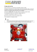
Operation
Note!
-
Do not store the suction unit in a damp or very cold (frost) environment. Otherwise
there is no guarantee that the installed pump will function properly.
-
Caution!
-
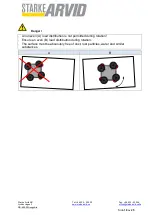
Always ensure that the suckers are not placed on sharp edges because this could
damage the sucker lips. This would lead to leaks in the suction circuit, impairing
the functioning of the device.
-
Never place the machine with mounted suckers with the rubber surfaces of the
suckers on sandy or similar ground. This could damage the sealing lips of the
suckers. This would lead to leaks in the suction circuit, impairing the functioning of
the device. Or the grains of sand or similar substances could be pressed into the
rubber surfaces, leading to damage to the upper surface of the transported goods.
-
Caution!
-
Do not allow heavy rain to fall on the device.
-
Do not place the device in water.
-
Do not convey loads over persons or machines. Cordon off the area under hang-
ing transported goods with wide clearance.
i


