0
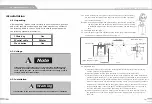
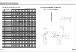
Shaft dowel pin
Outer adjusting spacers
Side plate G
0
0
0
0
A
Auxiliary wheel
•
Side-plate S
B
Inner adjusting spacers
A
Suspender T
(Fig.4.7)
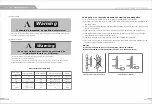
Warning
It is forbidden to link the power supply before
the completion of installation.
Warning: please always fix with nuts
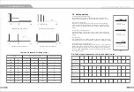
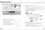
(c) Install the trolley on the traversing rail.
1. Under an exceptional circumstance, the most convenient
installation way is to make the hoist trolley installed in the
traveling rail from the end of the rail.
2. If it is not available with the first way, please do installation
as the following:(See Fig.12)
1) Remove the bolt from the suspension shaft hole A. Then
insert it into the hole B. Fix it with split pin.
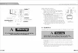
2) Outward stretch side plate G and side plate S. Lift the
trolley up to the traveling rail to keep both sides of wheel
rail and traveling rail at the same level.
Side plates
Side plate G
Fig 4.8
3) Firstly support one side plate (G or S), then push the other
side plate (S or G) with strength to prevent its shedding from
rail. Keep the wheel rail and the traveling rail at the same level.
Trolley with the hoist
mounting to traversing rail
4) Remove the bolt from the hole B, insert it to the hole A, and fix
it with split pin.
5. Operation
After the above-mentioned test and operation testing, the hoist can be normally operated.
A
Warning
The heavy load may result in unexpected risks, so all "safety rules"
(refer to chapter 3) must be fully followed, and the operator must pay
attention to and do perform the following when in operation:
{l) Before operation, the operator must have a clear and unobstructed view of the whole
working area.
(2) Before operation, the operator must check whether the whole working area is safe and
free of risks.
(3) When the trolley is operated, the operator must be careful to prevent from the situation
that the reverse force caused by swing of the weights, may be over the load of trolley
while changing the trolley operation direction.


