3. Door Open message will not disappear
Actions:
a)
The CybaMICRO controller has a monitored door switch system.
Consequently there are two limit switches monitoring each baler
door.
Door 1 Limit Switch is closed when the door is shut, and Door 2
Limit Switch is open when the door is shut. When the door is
open Door 1 Limit Switch must open and Door 2 Limit Switch must
close. Any abnormality in this switch operation will be detected,
and the controller will default to the safe state which is the Door
Open. Check the operation of both switches.
Magnetic door switches also have two separate contacts encapsu
lated in a single switch unit. They also switch in the same pattern
as above.
b)
Check carefully the wiring to both door limit switches. Also look along
the length of the wire harness for signs of damage.
c)
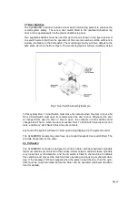
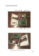
Any detected fault in the PCB monitoring system will also default to
Door Open. Possible PCB fault. The PCB has two door open
LEDs labeled Door(S) and Door(M). These are provided for fault
finding, and LED indicates the individual state of the dual redun
dant door switch monitoring circuitry.
They do not indicate the
state of each switch contact.
In normal operation when the door
is closed Door(S) will go out followed by Door(M) a second or so
later. If calling for service note any abnormality in this function.
7.0 Motor Reversing Plug System
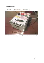
The CybaMICRO 2011 controller is fitted with two motor sockets. The motor cable
can be plugged into either, however the motor direction will be reversed depending on
which socket it is plugged into. Both motor sockets are simultaneously powered when
the contactor closes, but two phase wires are swapped in one socket causing the mo-
tor to run in the opposite direction. This allows the correct motor direction to be se-
lected without the need to call a qualified electrician.
NOTE: Never swap the motor plug into a different socket while the controller is
switched on. Always fit the cap to the unused socket.
Page 13


