background image

IMPORTANT SAFETY NOTICE 

!

 

Your StarLogixs CybaMICRO Controller provides vital safety features in your baler. If the 
Controller has been damaged always have it checked by a person qualified for electrical 
maintenance before  operating the baler. 

 

Check all power leads and plugs for damage. If damage is found switch off and disconnect 
from supply, and have repaired by a person qualified for electrical maintenance.  

 

The ‘door closed’ sensors are critical to the safe operation of the baler.  If they are dam-
aged  or  the  mechanism  driving  them  is  damaged  never  attempt  to  use  the  baler  before 
calling an approved service agent. 

      The Controller has lethal voltages inside

.  

 


N

EVER


OPEN


OR


ATTEMPT


TO


SERVICE

.  

 

 N

EVER


REMOVE


OR


ATTEMPT


TO


REMOVE


THE


FRONT


COVER

 

 N

O


USER


SERVICEABLE


PARTS


OR


ADJUSTMENTS


INSIDE

 

 D

O


NOT


DIRECTLY


EXPOSE


C

ONTROLLER


TO


RAIN


OR


HIGH


PRESSURE


WATER


JETS

.


 

S

HOULD


YOU


LEAVE


YOUR


BALER


UNATTENDED


FOR


A


PERIOD


OF


TIME

IT


IS


STRONGLY


REC-

OMMENDED


THAT


YOU


SWITCH


THE


POWER


OFF


AND


REMOVE


THE


KEY

.  

 

A

NY


UN

-

AUTHORISED


ACCESS


INTO


THE

 C

ONTROLLER


WILL


VOID


WARRANTY

.  

Note to Serviceman 

Always obtain the latest version of service manual from 
 www.starlogixs.com.au before attempting to service the control system.  
Do  not  substitute  items  noted  in  the  service  manual  as  critical  components  in  the  safety 
systems. 

Declaration of Conformity  

The CybaMICRO Controller is designed to control baling presses and conforms with the follow-
ing standards:  


AS/NZS20641: 1997 


(EC/CISPR11: 1992) 

 
And is manufactured under Australian Communications Authority C-Tick approval number.  
The safety door switches are monitored and have in-built redundancy.  


Machine Model: _______________________________ 


Serial Number: ________________________________ 


N10728

Page 2 

Summary of Contents for CybaMICRO 2011

Page 1: ...R ELECTRONIC CONTROL SYSTEM Page 1 CybaMICRO 2011 Model...

Page 2: ...S OR ADJUSTMENTS INSIDE DO NOT DIRECTLY EXPOSE CONTROLLER TO RAIN OR HIGH PRESSURE WATER JETS SHOULD YOU LEAVE YOUR BALER UNATTENDED FOR A PERIOD OF TIME IT IS STRONGLY REC OMMENDED THAT YOU SWITCH TH...

Page 3: ...sic Controller Function P6 2 1 Operation of the Pressure Switch and Travel Switch P6 2 2 Full Bale Detection P7 2 3 Door Switches P8 2 4 Tilt Switch P8 3 0 CybaMICRO Display P9 3 1 Status Messages P9...

Page 4: ...the baler In particular the controller monitors a dual safety door switch with a fully re dundant circuit that will detect a single failure in either the door switches or the monitor circuit The cont...

Page 5: ...ergency stop causes controller Power LED to go out and ma chine to immediately stop Also check that opening top baler door causes Door Open to be displayed in the System Monitor The baler pressing app...

Page 6: ...en the power is initially switched on pressing the OPERATE button will cause the baler to retract Also if a full bale condi tion is sensed the cycle will terminate with the baler pressing apparatus lo...

Page 7: ...s is not fitted Consequently the Plastic Full condition is reset as soon as the baler is retracted However the travel switch can not eliminate the need for the hydraulic pressure switch As the baler f...

Page 8: ...the door is changed from open to shut or shut to open the contacts in both switches must change state That is when the door is opened Door 1 Limit Switch must open its con tacts and Door 2 Limit Swit...

Page 9: ...ains when the door is shut Ready to Retract Indicates the baler is ready to retract when the OPERATE button is pressed Ready to Press Indicates the baler is ready to perform a compaction cycle when th...

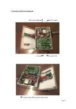
Page 10: ...Page 10 Controller PCB Motor Contactor Motor Overload Relay 2A Fuse Power Supply PCB under Controller PCB 4 0 Location of Internal Components...

Page 11: ...or tilt sensor wiring SL A LA100925 2 2kW Motor contactor 24Vdc coil SL A LA100209 Motor overload relay SL S PS 45 24 Power supply PCB SL X CM PCB2011 Controller PCB SL S CEB2 2amp 20mm glass fuse SL...

Page 12: ...B may be blown or the 4A fuse on the power supply PCB may be blown Ensure the mains plug is disconnected and tagged out before opening the controller If the 4A power supply fuse continually blows repl...

Page 13: ...or Open Possible PCB fault The PCB has two door open LEDs labeled Door S and Door M These are provided for fault finding and LED indicates the individual state of the dual redun dant door switch monit...

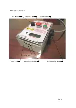
Page 14: ...Page 14 8 0 Location of Controls Key Switch Emergency Stop Operate Button Status LEDs Main Wiring Connector Motor Reversing Sockets Serial No...

Page 15: ...Page 15 9 0 Main Wiring Harness...

Page 16: ...l be charges rendered for repairs to the product made after the expiration of the aforesaid twelve month warranty period This warranty gives you specific legal rights and you may have other rights whi...

Reviews: