background image

1.0. Suggested Conditions of Use  


1.1. Qualified Operators 

 
Operator: 
 

Qualified  to  operate  the  control  unit  in  all  normal  day  to  day  functions  of  the 

baler. 
 
Person Qualified for Electrical Maintenance 
 

Must  be  trained  by  the  manufacturer  and  hold  appropriate  trade  qualifications 

for the service of mains electrical equipment and safety related electronic equipment. 
 
Safety Manager: 
 

The Safety Manager is the person in charge, liable for protection and prevention 

from working risks.  The safety manager will make sure that all persons operating with 
the machine receives all instructions concerning their jobs, as herewith contained, in-
cluding and beginning from installation and machine starting. 
 
Manufacturer: 
It  is  necessary  to  contact  StarLogixs  for  any  operation  not  expressly  covered  in  the 
present manual and assigned to  any of the professionally qualified operators as listed 
above.  

1.2. Description of the Controller  

 
The CybaMICRO controller is an electronic industrial control system designed to pro-
vide control and safety features for bailing machines. The controller co-ordinates con-
trol  of  the  baler  electronic  motor  and  hydraulic  solenoid  valves,  whilst  monitoring  a 
number of sensor devices to allow it to respond appropriately to pressing conditions in 
the baler. In particular the controller monitors a dual safety door switch with a fully re-
dundant circuit that will detect a single failure in either the door switches or the monitor 
circuit.  
The controller houses mains voltage and should only be serviced by qualified persons.  
It should be maintained in accordance with relevant electrical safety standards.  
 

1.3. Situation of Normality  

 
It is absolutely necessary that the controller is used in the conditions suggested by the 
present manual of use and maintenance. It is not allowed to misuse the controller or 
its safety devices nor to use the machine in abnormal conditions. 
We wish to point out below some suggestions, to be carefully considered by the op-
erator in order to avoid abnormal conditions of use. 

 

Do not operate the controller if it is not properly attached to the baler. 

 

Do not operate the controller if door sensors, emergency stops or other electri-
cal components are damaged, or not functioning. 

 

It  is  strictly  prohibited  that  persons  other  than  the  operator  approach  the  ma-
chine. 

 

The controller shall not be installed and shall not operate in an explosive envi-
ronment. 

 

The controller shall never be washed with jets of water or flammable liquids. 

 

Cleaning and maintenance operations shall be performed by qualified persons.  

 

The  operator  shall  always  perform  periodical  safety  checks,  as  required  by 
safety rules. 

 

The controller should be protected from direct exposure to rain and sunlight. 

Page 4 

Summary of Contents for CybaMICRO 2011

Page 1: ...R ELECTRONIC CONTROL SYSTEM Page 1 CybaMICRO 2011 Model...

Page 2: ...S OR ADJUSTMENTS INSIDE DO NOT DIRECTLY EXPOSE CONTROLLER TO RAIN OR HIGH PRESSURE WATER JETS SHOULD YOU LEAVE YOUR BALER UNATTENDED FOR A PERIOD OF TIME IT IS STRONGLY REC OMMENDED THAT YOU SWITCH TH...

Page 3: ...sic Controller Function P6 2 1 Operation of the Pressure Switch and Travel Switch P6 2 2 Full Bale Detection P7 2 3 Door Switches P8 2 4 Tilt Switch P8 3 0 CybaMICRO Display P9 3 1 Status Messages P9...

Page 4: ...the baler In particular the controller monitors a dual safety door switch with a fully re dundant circuit that will detect a single failure in either the door switches or the monitor circuit The cont...

Page 5: ...ergency stop causes controller Power LED to go out and ma chine to immediately stop Also check that opening top baler door causes Door Open to be displayed in the System Monitor The baler pressing app...

Page 6: ...en the power is initially switched on pressing the OPERATE button will cause the baler to retract Also if a full bale condi tion is sensed the cycle will terminate with the baler pressing apparatus lo...

Page 7: ...s is not fitted Consequently the Plastic Full condition is reset as soon as the baler is retracted However the travel switch can not eliminate the need for the hydraulic pressure switch As the baler f...

Page 8: ...the door is changed from open to shut or shut to open the contacts in both switches must change state That is when the door is opened Door 1 Limit Switch must open its con tacts and Door 2 Limit Swit...

Page 9: ...ains when the door is shut Ready to Retract Indicates the baler is ready to retract when the OPERATE button is pressed Ready to Press Indicates the baler is ready to perform a compaction cycle when th...

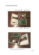
Page 10: ...Page 10 Controller PCB Motor Contactor Motor Overload Relay 2A Fuse Power Supply PCB under Controller PCB 4 0 Location of Internal Components...

Page 11: ...or tilt sensor wiring SL A LA100925 2 2kW Motor contactor 24Vdc coil SL A LA100209 Motor overload relay SL S PS 45 24 Power supply PCB SL X CM PCB2011 Controller PCB SL S CEB2 2amp 20mm glass fuse SL...

Page 12: ...B may be blown or the 4A fuse on the power supply PCB may be blown Ensure the mains plug is disconnected and tagged out before opening the controller If the 4A power supply fuse continually blows repl...

Page 13: ...or Open Possible PCB fault The PCB has two door open LEDs labeled Door S and Door M These are provided for fault finding and LED indicates the individual state of the dual redun dant door switch monit...

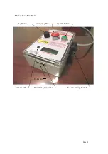
Page 14: ...Page 14 8 0 Location of Controls Key Switch Emergency Stop Operate Button Status LEDs Main Wiring Connector Motor Reversing Sockets Serial No...

Page 15: ...Page 15 9 0 Main Wiring Harness...

Page 16: ...l be charges rendered for repairs to the product made after the expiration of the aforesaid twelve month warranty period This warranty gives you specific legal rights and you may have other rights whi...

Reviews: