3-16
Expansion Board Installation
Chapter 3 - Installation
STARPLUS STSe - Installation Manual
August 2005
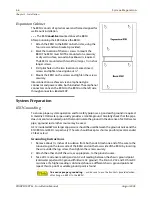
T1 Interface Board
The optional T1IB provides the T1 (1.544Mbps, 24 channel) interface circuit, control circuitry,
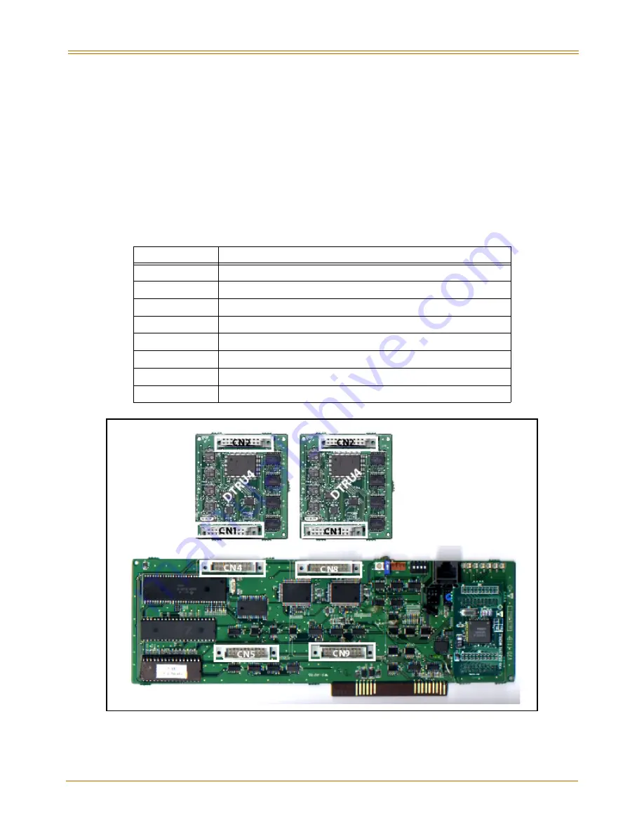
and synchronous clock control circuits. Up to two DTMF tone detection units (DTRU4) can
optionally be installed on the T1IB.
The system can be equipped with one T1IB and it can be installed in slots 5, 6, or 7 of the BKSU
or in slots 11, 12, or 13 in the EKSU. The Phase Lock Loop Unit (PLLU) must be installed in the
BKSU for the T1 card to operate properly.
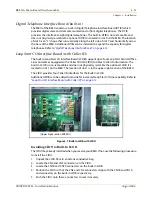
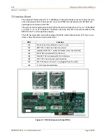
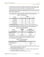
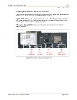
The T1IB has eight LEDs on the front edge of the PCB which indicate errors of T1 line, in-use
status, and synchronous clock enable status.
Figure 3-7: T1IB (24 channel) with two DTRUs
LED #
Function
LD1
IN USE At least one of the 24 circuits is in use
LD2
RED T1IB is in Red alarm due to any alarm
LD3
Loopback (H/W TEST - normal call processing is not available)
LD4
BLUE T1IB has detected RX_BLUE alarm
LD5
YELLOW: T1IB has detected RX_YELLOW alarm
LD6
OOF T1IB is Out of Frame synchronization
LD7
RCL T1IB receives Carrier Loss (unplugged from the cable)
LD8
CLOCK Clock Enable/Disable
Summary of Contents for STSe Key System
Page 1: ...August 2005 Issue 1 0 STARPLUS STSe Key Systems Installation Manual TM...
Page 4: ......
Page 10: ...vi Figures STARPLUS STSe Installation Manual August 2005...
Page 12: ...viii Tables STARPLUS STSe Installation Manual August 2005...
Page 14: ...N O T E S...
Page 22: ...N O T E S...
Page 30: ...N O T E S...
Page 68: ...3 40 Door Box Chapter 3 Installation STARPLUS STSe Installation Manual August 2005...
Page 70: ...N O T E S...
Page 94: ...iv Index STARPLUS STSe Installation Manual August 2005...

