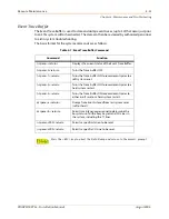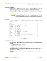
Remote Maintenance
4-11
Chapter 4 - Maintenance and Troubleshooting
STARPLUS STSe - Installation Manual
August 2005
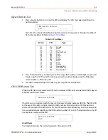
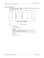
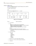
Station Configuration
Figure 4-3
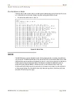
is a configuration of the
STARPLUS
STSe
System and displays what is printed when the
installer types
d<space>s1
at the maint> prompt.
Figure 4-3: Station Configuration
Column
Indicates the following …
1
Station Number
2
Station Type (keyset, DSS, SLT)
Keyset - ID 0 = Key station
DXX 1 = DSS Map 1
DXX 2 = DSS Map 2
SLT - ID 6 = SLT
SLT w/Lamp - ID 7 = SLT w/Message Waiting
3
Status
OOS
status can indicate the entire card is out of service; a specific station is
not installed; or installed but not operational.
INS
status can indicate a specific station is installed and operating correctly.
4
Whether or not the station has an LCD Display
5
State of the device
maint>d s1
SLOT CARD CKTS SERV STAT BRD OPTS FW VER.
--------- ---- ---- ----------- ---------- ---------
01 DTIB 8 INS 0 00-0
STA
FLEX-FIX-PORT TYPE STATUS LCD STATE
------------- -------- ---------- ----- -----
100-100-002 24BTN INS Y IDLE
101-101-003 24BTN INS Y IDLE
102-102-004 24BTN INS Y IDLE
103-103-005 24BTN OOS Y ID UNKNOWN
104-104-006 24BTN OOS Y ID UNKNOWN
105-105-007 24BTN OOS Y ID UNKNOWN
106-106-008 24BTN OOS Y ID UNKNOWN
107-107-009 24BTN OOS Y ID UNKNOWN
Summary of Contents for STSe Key System
Page 1: ...August 2005 Issue 1 0 STARPLUS STSe Key Systems Installation Manual TM...
Page 4: ......
Page 10: ...vi Figures STARPLUS STSe Installation Manual August 2005...
Page 12: ...viii Tables STARPLUS STSe Installation Manual August 2005...
Page 14: ...N O T E S...
Page 22: ...N O T E S...
Page 30: ...N O T E S...
Page 68: ...3 40 Door Box Chapter 3 Installation STARPLUS STSe Installation Manual August 2005...
Page 70: ...N O T E S...
Page 94: ...iv Index STARPLUS STSe Installation Manual August 2005...


