Startco Engineering Ltd.
Page 3
SE-701 Ground-Fault Monitor
Rev. 5
Pub. SE-701-M, December 14, 2006.
If Switch 5 is in the LATCHING position, a trip
remains latched until the RESET switch is pressed, the
remote-reset terminals are momentarily shorted, or the
supply voltage is cycled. Cycling the supply voltage will
not reset (black) the fluorescent flag.
If Switch 5 is in the AUTORESET position, a trip will
reset when the fault is removed. The fluorescent flag will
not reset until the RESET switch is pressed or the remote-
reset terminals are momentarily shorted. Cycling the
supply voltage will not reset the fluorescent flag unless
the remote-reset terminals are shorted.
2.2.4 T
EST
The TEST switch is used to test the ground-fault
circuit, the indication, and the output relay. When the
TEST switch is pressed for one second; the circuit will
trip, trip indication will come on, and the output relay will
operate. If high-current inhibit has been selected, the
inhibit indicator will come on.
2.3 F
RONT
-P
ANEL
I
NDICATION
2.3.1 P
OWER
The green LED labeled PWR indicates the presence of
supply voltage.
2.3.2 G
ROUND
-F
AULT
T
RIP
The red LED and the fluorescent flag, labeled TRIP,
indicate a trip. A solid red LED indicates a ground-fault
trip and a flashing LED indicates a trip initiated by a CT
fault.
2.3.3 I
NHIBIT
The yellow LED labeled INHB indicates that output-
relay operation was inhibited during a high-current
ground fault. When a ground-fault trip occurs, both the
TRIP and INHB LED’s will be ON. Inhibit indication is
reset when the ground-fault trip is reset. Inhibit operation
and indication will not respond if Switch 2 is in the
INHIBIT OFF position.
2.4 A
NALOG
O
UTPUT
The non-isolated, 0- to 5-V analog output indicates
ground-fault current sensed by the ground-fault CT. The
output is 5 V at 100% of the CT-primary rating.
3. I
NSTALLATION
An SE-701 can be surface- or DIN-Rail-mounted. See
Fig. 1. Panel mounting requires a PMA-55 Panel-Mount
Adapter. See Fig. 6.
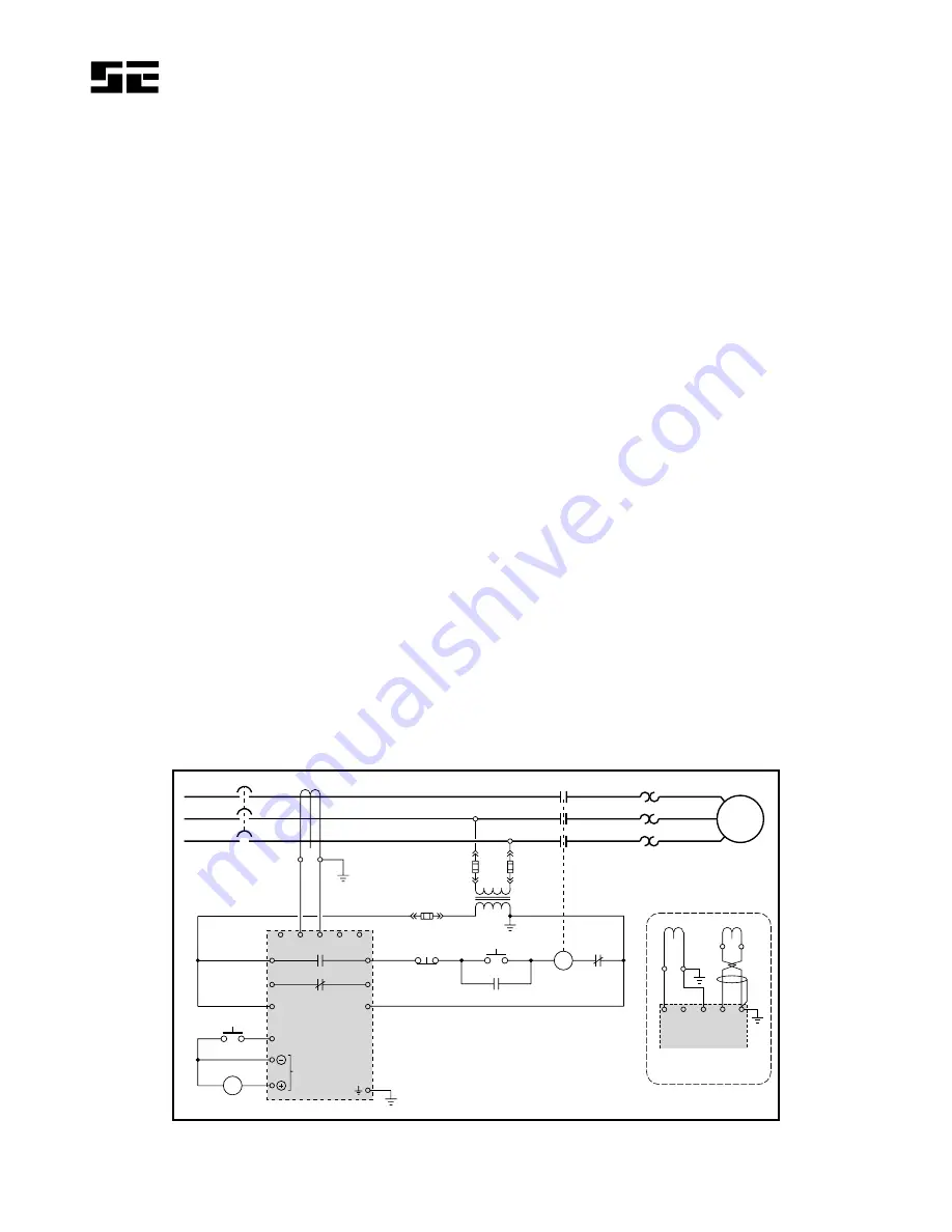
Pass the phase conductors through the CT window as
shown in Fig. 2 (for 4-wire and single-phase systems, also
pass the neutral conductor through the CT window). Do
not pass ground conductors through the CT window. In
applications that require shields or drain wires to pass
through the CT window, return them through the CT
window before connecting them to ground. If a ground
fault CT with a 5-A secondary is used, connect it to
terminals 2 and 3 (terminals 1 and 3 with a 1-A
secondary) and ground terminal 3. If an EFCT-x is used,
connect it to terminals 4 and 5, connect the shield to
terminal 5, and ground terminal
5. Remove the
connection to terminal 9 for dielectric-strength testing
—all inputs and outputs have ANSI/IEEE C37.90 surge-
protection circuits that conduct above 300 Vac. See
Figs. 3, 4, and 5 for sensitive EFCT-x dimensional
drawings.
XX
5
X:
1 A 5 A
C
STOP
START
1M
1M
SE-701
RS
REMOTE RESET
V
LEAKAGE
ANALOG
OUTPUT
S1
S2
O/L
L
N
1
2
4
3
5
13
14
15
16
6
7
8
9
L1
11
10
L2
ISOLATED CONTACTS
1 A 5 A
C
S1 S2
1
2
3
4
5
SE-701
EFCT-X
ALTERNATE CT
CONNECTIONS
XXX:1
OR
Technical Information 11.1
provides additional
information on CT selection.
FIGURE 2. Typical Connection Diagram.


