


Startco Engineering Ltd.
Page 5
SE-701 Ground-Fault Monitor
Rev. 5
Pub. SE-701-M, December 14, 2006.
215.0
215.0
215.0
162.0
31.0
25.0
198.0
8.5
8.5
52.3
60.0
64.0
31.0
236
MAX
(8.46)
(8.46)
(8.46)
(6.38)
(1.22)
(0.98)
(7.80)
(0.33)
(0.33)
(2.06)
(2.36)
(2.52)
(1.22)
(9.29)
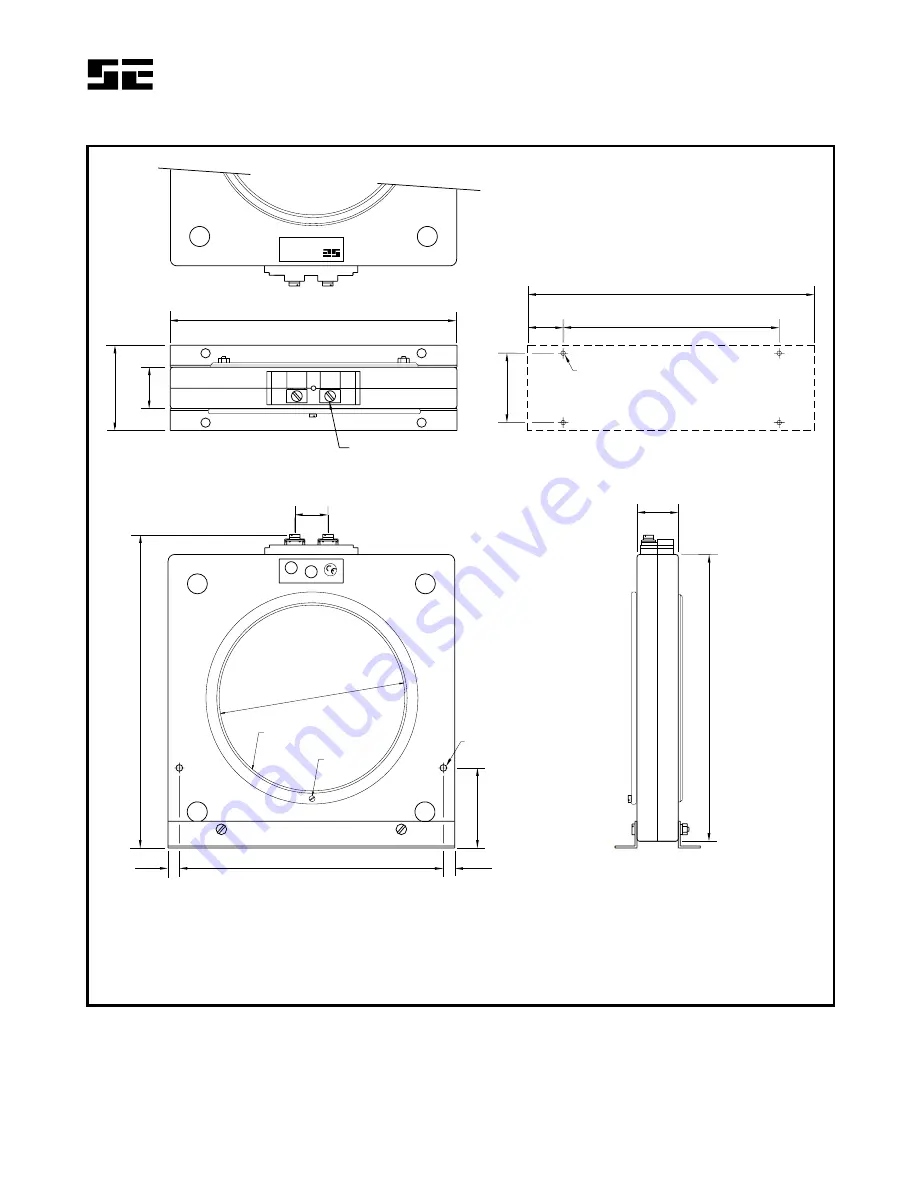
M5 SCREWS
TOP
MOUNTING DETAIL
M4 OR 8-32 TAP
SIDE
FRONT
EFCT-2EARTH
FAULT
CT
600V
INSULATIONC
LASS
STARTCO
EN
GIN
EE
RIN
GL
TD
.
5.0 (0.20) DIA
NOTES:
1. DIMENSIONS IN MILLIMETRES (INCHES).
MOUNTING SCREWS: M4 OR 8-32.
2.
P
P
S S
2
2
1
1
S
P
1
1
139.7
(5.50)
BONDING
SCREW
FLUX CONDITIONER
(INCLUDED)
26.5
(1.04)
FIGURE 4. EFCT-2 Outline and Mounting Details.


