Quick-Start Guide
To view manuals, FAQs, videos, drivers, downloads, technical drawings, and more, visit www.startech.com/support.
Manual Revision: November 22, 2022
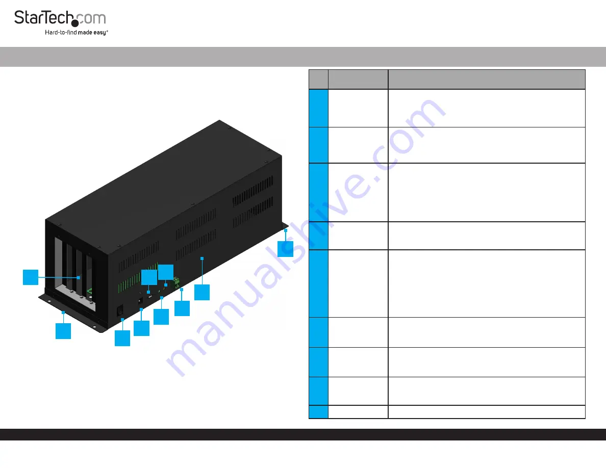
Product Diagram (4PCIE-PCIE-ENCLOSURE)
PCIe Expansion Chassis
PCIe 2.0 to 4 PCIe Slots Expansion Chassis - USB Type-C
Port/LED/
Connector
Function
1
PCIe Expansion
Slots
• Install up to
Four PCIe cards
• PCIe version 2.0 x1 slots
• 10 Gbps aggregate host bandwidth
• Full length cards supported
2
Mounting
Brackets
• (Optional) Allows for a permanent installation of the
PCIe
Expansion Chassis
to a flat and stable surface
•
Mounting Holes
at the
Front
and
Back
of the
PCIe
Expansion Chassis
secure the
Mounting Brackets
3
On/Off Switch
• Turns the
Expansion Chassis On
or
Off
• The correct sequence to power the device:
• Power on: Power
On
the
PCIe
Expansion Chassis
first, then the
Host Computer
• Power off: Power
Off
the
Host Computer
first, then
the
PCIe Expansion Chassis
4
DC Power Port
• Connect the
PCIe
Expansion Chassis
to a
Power Source
using the included
Power Adapter
• Recommended 12 V and 3 A. Supports 12 to 24 V input
5
USB Type-C
Connector
• Used to connect the
PCIe
Expansion Chassis
to a
Host
Computer
• If the
USB Type-C Cable
is disconnected during use,
the
Host Computer
must be restarted to reestablish the
connection
• For a secure and correct cable connection, threaded
holes around the
USB Type-C Connecto
r allow to
Screw-lock
the included
USB Type-C Cable
6
USB Type-C LED
Indicator
• Indicates if the included
USB Type-C-Cable
is on the
correct orientation. The cable is not reversible
• Solid Green = Correct orientation
7
Power LED
Indicator
• Indicates if the
On/Off Switch
is turned
On
or
Off
• Solid Red = On
• Off = Off
8
Terminal Block
Connector
• Connect the
PCIe
Expansion Chassis
to a
DC Power
Source
• Recommended 12 V and 3 A. Supports 12 to 24 V input
9
Metal Cover
• Remove the
Metal Cover
to install the
PCIe cards
3
7
4
1
6
5
8
9
2
*Product may vary from image
2


