Quick-Start Guide
To view manuals, FAQs, videos, drivers, downloads, technical drawings, and more, visit www.startech.com/support.
Manual Revision: November 22, 2022
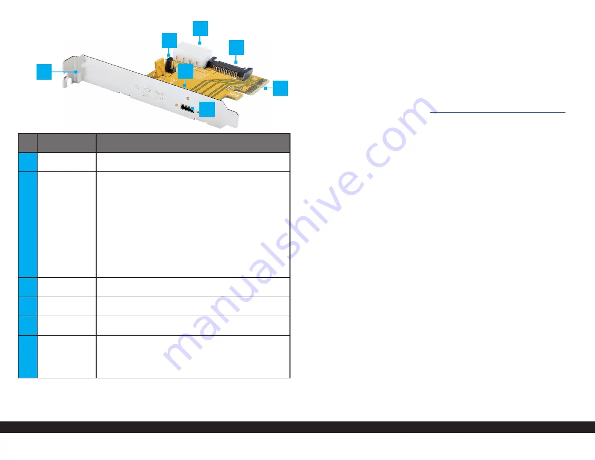
PCIe Host Adapter Card
Port/LED/
Connector
Function
1
Bracket
• Secures the card to the
Host Computer Case
. The
Full-
height Bracket
comes pre-installed
2
JP1 Jumper
(BUS PWR)
JP2 Jumper
(
WAKE) (not
visible in image)
• Enables the
PCIe Host Adapter Card
to provide power to
the
PCIe
Expansion Chassis
via the
USB Type-C Cable
.
• Three position are available for
JP1
: 12V, NC
(default), and 5V
• To inject power via the
PCIe Host Adapter Card
it
must be used in combination with
JP1
and
JP2
on
the
PCIe
Expansion Chassis
• Enables the
PCIe WAKE# Pin
, and allows to wake the
Host Computer
when
Wake-on-LAN (WoL) Packets
have been received.
A
WoL
capable
Network Card
must
be installed in the
PCIe Expansion Chassis
.
• Two positions are available for
JP2
: DIS (disabled)
and ENA (default)
3
LP4 Power
Connector
•
Optional:
Connect the
Host Computer Power Supply
4
SATA Power
Connector
•
Optional:
Connect
the
Host Computer Power Supply
5
PCIe x2
Connector
• Insert into a
PCIe Slot
on the host Host Computer
6
USB Type-C
Connector
• Used to connect the
PCIe Host Adapter Card
to the
PCIe
Expansion Chassis
• For a secure and correct cable connection, threaded
holes around the
USB Type-C Connecto
r allow to
Screw-
lock
the included
USB Type-C Cable
Package Contents
• PCIe to PCIe Expansion Chassis x 1
• PCIe Host Adapter Card
• 6ft (1.8m) USB Type-C to C Male to Male Cable x 1
• Low-Profile Bracket x 1
• Power Adapter x 1
• Terminal Block Connector x 1
• Mounting Brackets x 2
• Mounting Brackets Screws x 4
• Quick-Start Guide x 1
Requirements
For the latest requirements, please visit
www.startech.com/4PCIE-PCIE-ENCLOSURE
• Host Computer with an available PCIe Slot (x2, x4, x8, or x16)
• Phillips head screwdriver
Installation
WARNING!
Static electricity
can severely damage the PCIe card(s) ensure that you are adequately
grounded before you open your Host Computer case or touch the PCIe card(s). You
should wear an anti-static strap or use an anti-static mat when installing any Host
Computer component. If an anti-static strap isn’t available, discharge any built-up
static electricity by touching a large grounded metal surface for several seconds. Only
handle the PCIe card(s) by the edges and don’t touch the golden connectors.
Install the PCIe Host Adapter Card
1. Turn
Off
the
Host
Host Computer
and any
Peripheral Devices
that are connected
to it (e.g. printers, external hard drives, etc.).
2. Unplug the
Power Cable
from the back of the
Host Computer
.
3. Disconnect any
Peripheral Devices
that are connected to the
Host Computer
.
4. Remove the
Cover
from the
Host Computer Case
. Consult the documentation that
came with the
Host Computer
for details about doing this safely.
5. Locate an available
PCIe Slot
and remove the corresponding
Slot Cover Plate
from
the back of the
Host Computer Case
. Consult the documentation that came with
the
Host Computer
for details about doing this safely. The
PCIe Host Adapter Card
works in
PCIe x2
,
x4
,
x8
, or
x16
Slots
.
6. Gently insert the
PCIe Host Adapter Card
into the
PCIe Express Slot
and fasten the
Bracket
to the back of the
Host Computer Case
.
Note:
If you install the PCIe Host Adapter Card into a small form factor or a low-profile
desktop system, it may be necessary to replace the pre-installed standard full-height
bracket with the included low-profile bracket.
8. (Optional) Connect a
SATA Power Cable
or
LP4
from the
Host Host Computer
Power Supply
.
9. Return the
Cover
onto the
Host Computer Case
.
1
3
4
6
5
2
2


