background image

13

To view manuals, videos, drivers, downloads, technical drawings, and more visit www.startech.com/support

Install the Leveling Feet

Note: 

Flip the 

Rack

 onto its side to complete this step. 

1. 

Insert the four Leveling Feet into the four holes located in 

the bottom of each 

Base Bracket.

2. 

Tighten each one of the 

Leveling Feet

 by hand, or with a 

14 

mm Wrench

(Figure 8)

Install the Casters

Notes: 

Flip the 

Rack

 onto its side to complete this step. 


Two people may be required to complete this step. 

1. 

Align the four holes in a 

Caster 

with the four holes in the 

bottom of the 

Rack

.

Figure 7

Summary of Contents for 4POSTRACKxU

Page 1: ...l Revision 12 03 2019 User Manual For the latest information and specifications visit www startech com 4POSTRACKxU Adjustable 4 Post Open Frame Server Rack Actual product may vary from photos SKU 4POSTRACKxU ...

Page 2: ... for illustrative purposes only and do not represent an endorsement of a product or service by StarTech com or an endorsement of the product s to which this manual applies by the third party company in question Regardless of any direct acknowledgement elsewhere in the body of this document StarTech com hereby acknowledges that all trademarks registered trademarks service marks and other protected ...

Page 3: ... sure that you install the enclosure in an area that can handle the combined weight of the enclosure and the equipment that you intend to place inside of the enclosure This product requires an earth ground connection Do not use this product without an earth ground connection Varningar Se till att du monterar produkten i enlighet med instruktionerna Överskrid inte produktens vikt kapacitet Överbela...

Page 4: ...eur et n empilez pas le rack sur un autre rack N approchez aucun liquide du rack de serveur Veillez à installer le rack de serveur dans un endroit pouvant supporter le poids combiné du rack et des équipements que vous comptez placer à l intérieur Ce produit nécessite un raccordement à la terre N utilisez pas ce produit sans raccordement à la terre Warnhinweise Beachten Sie bei der Montage dieses P...

Page 5: ...o senza assistenza Pericolo di ribaltamento L estensione di più componenti dal box esterno aumenta il rischio di ribaltamento del box esterno Per evitare questo rischio non estendere più di un componente dal box esterno Non collocare oggetti sul box esterno e non impilare un box esterno sopra un altro Tenere il box esterno lontano dai liquidi Assicurarsi di installarlo in un punto che possa sorreg...

Page 6: ...se en exteriores La caja es extremadamente pesada Nunca intente mover o alzar esta caja sin la debida asistencia de otra persona Peligro de vuelco Añadir a esta caja varios componentes aumenta las posibilidades de peligro de vuelco de la caja Para evitar dicho riesgo no añada más que un solo componente No coloque ningún elemento encima de la caja y no apile la caja encima de otra caja Mantenga cua...

Page 7: ...t u de behuizing installeert op een plaats die geschikt is voor het gecombineerde gewicht van de behuizing en de apparatuur die u in de behuizing wilt plaatsen Dit product vereist een geaarde verbinding Gebruik dit product niet zonder een geaarde verbinding 注意 必ず取扱説明書に従って本製品の組み立てを行って下さい 本製品で定められた可搬重量を超えないようにして下さい 規定された 重量を超えた場合 怪我や物的損害が発生することがあります 本製品 は次の可搬重量に対応していいます キャスター静止時 544 kg キ ャスター動作時 300...

Page 8: ...tements i Warning Statements ii Product Diagram 1 Expanded View 1 Package Contents 2 Requirements 7 Installation 7 Set the Mounting Depth 7 Assemble the Rack 9 Install the Leveling Feet 13 Install the Casters 13 Install the Cable Management Hooks 14 Ground the Rack 15 Operation 16 Adjust the Leveling Feet 16 Warranty Information 17 ...

Page 9: ...l drawings and more visit www startech com support Product Diagram Expanded View 1 Left Vertical Rails x 2 5 Center Sections x 4 2 Right Vertical Rails x 2 6 Top Brackets x 2 3 Base Brackets x 2 18 Casters x 4 4 Corner Sections x 8 19 Leveling Feet x 4 ...

Page 10: ... view manuals videos drivers downloads technical drawings and more visit www startech com support Package Contents Left Vertical Rail Qty 2 Right Vertical Rail Qty 2 Base Bracket Qty 2 Corner Section Qty 8 ...

Page 11: ... view manuals videos drivers downloads technical drawings and more visit www startech com support Center Section Qty 4 Top Bracket Qty 2 M8 Bolt Qty 50 M8 Washer Qty 50 10 mm Wrench Qty 1 13 mm Wrench Qty 1 ...

Page 12: ...42U Qty 50 M6 Plastic Washers 8U 12U 15U 18U Qty 24 25U Qty 32 42U Qty 50 M6 Phillips Head Screw 8U 12U 15U 18U Qty 24 25U Qty 32 42U Qty 50 Cable Management Hooks 8U 12U Qty 4 15U 18U Qty 8 25U Qty 12 42U Qty 24 Hook Mounting Screws 8U 12U Qty 4 15U 18U Qty 8 25U Qty 12 42U Qty 24 ...

Page 13: ...w manuals videos drivers downloads technical drawings and more visit www startech com support Casters Qty 4 Leveling Feet Qty 4 M6 Screws Qty 18 M6 Flat Washers Qty 18 M6 Flange Nut Qty 18 Grounding Wires Qty 4 ...

Page 14: ...6 To view manuals videos drivers downloads technical drawings and more visit www startech com support M6 Grounding Wire Bolts Qty 4 M6 Grounding Wire Lock Washers Qty 4 ...

Page 15: ...round Connection Optional Spirit Bubble Level sold separately Installation Note Two people are required for the Rack assembly Set the Mounting Depth 1 Align the Corner Sections x 2 with the Center Sections x1 and slide the Corner Sections overtop of the Center Sections Figure 1 2 Determine the maximum required mounting depth for the Rack Mountable Equipment Review the Mounting Depth Chart to deter...

Page 16: ... 0 33 in 5 and 6 24 in 1 and 1 34 in 6 and 6 25 in 1 and 2 35 in 6 and 7 26 in 2 and 2 36 in 7 and 7 27 in 2 and 3 37 in 7 and 8 28 in 3 and 3 38 in 8 and 8 29 in 3 and 4 39 in 8 and 9 30 in 4 and 4 40 in 9 and 9 31 in 4 and 5 3 Slide the Corner Sections x 2 inward along the Center Sections x1 and align the Setting Numbers on the Center Sections with the first Rectangular Cutout on the Corner Sect...

Page 17: ...t they are parallel to one another Note The rack height numbers should be facing outwards and up 2 Insert one Center Section Assembly between the bottom of the Left Vertical Rail and the Right Vertical Rail Ensure the holes in the ends of the Center Section Assembly align with the holes in the bottom of the Left Vertical Rail and the Right Vertical Rail Note The Setting Numbers on the Center Secti...

Page 18: ...rt 4 Insert four M8 Bolts through four M8 Washers and into the holes in the Base Bracket Vertical Rails and the Center Section Assembly Figure 4 5 Tighten the M8 Bolts using the 13 mm Wrench 6 Repeat steps 3 to 5 to install the second Base Bracket 7 Lift the current assembly of parts upright Figure 4 ...

Page 19: ...r Section Assembly Note The rack height numbers on the Left Vertical Rail should be facing upright 10 Insert two M8 Bolts through two M8 Washers and into the holes in the Base Bracket that align with the Vertical Rails and the Center Section Assembly 11 Tighten the M8 Bolts using the 13 mm Wrench 12 Repeat steps 9 to 11 to install the Right Vertical Rail To view manuals videos drivers downloads te...

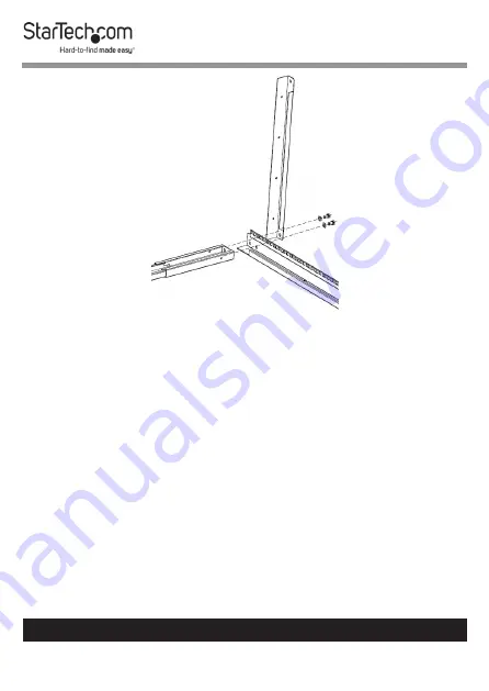
Page 20: ... a Center Section Assembly between the top of the Vertical Rails on the right hand side of the Rack 15 Place one Top Bracket on the top front side of the Rack Figure 6 16 Place a second Top Bracket on the top rear side of the Rack 17 Insert eight M8 Bolts through eight M8 Washers and into the holes in the Top Brackets and the tops of the Vertical Rails Figure 7 18 Tighten the M8 Bolts using the 13...

Page 21: ...Insert the four Leveling Feet into the four holes located in the bottom of each Base Bracket 2 Tighten each one of the Leveling Feet by hand or with a 14 mm Wrench Figure 8 Install the Casters Notes Flip the Rack onto its side to complete this step Two people may be required to complete this step 1 Align the four holes in a Caster with the four holes in the bottom of the Rack Figure 7 ...

Page 22: ...old the M6 Screws with the Pliers and tighten the M6 Flange Nuts with the 10 mm Wrench Note The M6 Screws will freely rotate if they are not held to prevent rotation 5 Repeat steps 1 to 4 to install the three remaining Casters Install the Cable Management Hooks 1 Align the Cable Management Hooks with the Cable Mounting Screw Holes along the back of the Rack 2 Insert a Hook Mounting Screw though th...

Page 23: ...being careful not to over tighten 4 Repeat steps 1 to 3 to install the remaining Cable Management Hooks Ground the Rack 1 Insert an M6 Screw through the Grounding Point on the Grounding Wire and into the Ground Hole located on the bottom of the Rack Figure 10 2 Run the Grounding Wire under the Rack s Frame 3 Connect the Grounding Wire to an Earth Ground Connection Figure 9 ...

Page 24: ...ww startech com support Operation Adjust the Leveling Feet Unscrew the Levelling Feet by hand and with a 14 mm Wrench until all four Levelling Feet are set to the same height and pressed firmly against the floor Note Use a Spirit Bubble Level to ensure the Rack is level Figure 10 ...

Page 25: ... damages whether direct or indirect special punitive incidental consequential or otherwise loss of profits loss of business or any pecuniary loss arising out of or related to the use of the product exceed the actual price paid for the product Some states do not allow the exclusion or limitation of incidental or consequential damages If such laws apply the limitations or exclusions contained in thi...

Page 26: ... tools StarTech com is an ISO 9001 Registered manufacturer of connectivity and technology parts StarTech com was founded in 1985 and has operations in the United States Canada the United Kingdom and Taiwan servicing a worldwide market Reviews Share your experiences using StarTech com products including product applications and setup what you love about the products and areas for improvement StarTe...

Reviews: