FCC Compliance Statement
This equipment has been tested and found to comply with the limits for a Class B digital device, pursuant to part 15 of the FCC Rules. These limits are designed to provide reasonable protection against
harmful interference in a residential installation. This equipment generates, uses and can radiate radio frequency energy and, if not installed and used in accordance with the instructions, may cause
harmful interference to radio communications. However, there is no guarantee that interference will not occur in a particular installation. If this equipment does cause harmful interference to radio or
television reception, which can be determined by turning the equipment off and on, the user is encouraged to try to correct the interference by one or more of the following measures:
• Reorient or relocate the receiving antenna.
• Increase the separation between the equipment and receiver.
• Connect the equipment into an outlet on a circuit different from that to which the receiver is connected.
• Consult the dealer or an experienced radio/TV technician for help.
Use of Trademarks, Registered Trademarks, and other Protected Names and Symbols
This manual may make reference to trademarks, registered trademarks, and other protected names and/or symbols of third-party companies not related in any way to
StarTech.com. Where they occur these references are for illustrative purposes only and do not represent an endorsement of a product or service by StarTech.com, or an endorsement of the product(s)
to which this manual applies by the third-party company in question. Regardless of any direct acknowledgement elsewhere in the body of this document, StarTech.com hereby acknowledges that all
trademarks, registered trademarks, service marks, and other protected names and/or symbols contained in this manual and related documents are the property of their respective holders.
Technical Support
StarTech.com’s lifetime technical support is an integral part of our commitment to provide industry-leading solutions. If you ever need help with your product, visit www.startech.com/support and access
our comprehensive selection of online tools, documentation, and downloads.
For the latest drivers/software, please visit www.startech.com/downloads
Warranty Information
This product is backed by a lifetime warranty.
In addition, StarTech.com warrants its products against defects in materials and workmanship for the periods noted, following the initial date of purchase. During this period, the products may be returned
for repair, or replacement with equivalent products at our discretion. The warranty covers parts and labor costs only. StarTech.com does not warrant its products from defects or damages arising from
misuse, abuse, alteration, or normal wear and tear.
Limitation of Liability
In no event shall the liability of StarTech.com Ltd. and StarTech.com USA LLP (or their officers, directors, employees or agents) for any damages (whether direct or indirect, special, punitive, incidental,
consequential, or otherwise), loss of profits, loss of business, or any pecuniary loss, arising out of or related to the use of the product exceed the actual price paid for the product. Some states do not allow
the exclusion or limitation of incidental or consequential damages. If such laws apply, the limitations or exclusions contained in this statement may not apply to you.
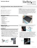
4. Position the rack right-side up (side panel locks at top) and drop
the top panel onto the top of the rack. Fasten to the frame using
M6 hex screws and the smaller Allen Wrench.
NOTE:
Ensure the corner caps are installed before attempting to
install the roof panel, otherwise the corners will not be level.
M6 Hex Screw
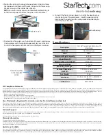
5. Position the 3 floor plates on the bottom of the rack, making sure
the two pieces with the cable management slots are at the end.
Fasten the floor plates with M5 screws and Phillips screw driver.
Cable
Management
Slot
Note the notches
in the end plate
corners
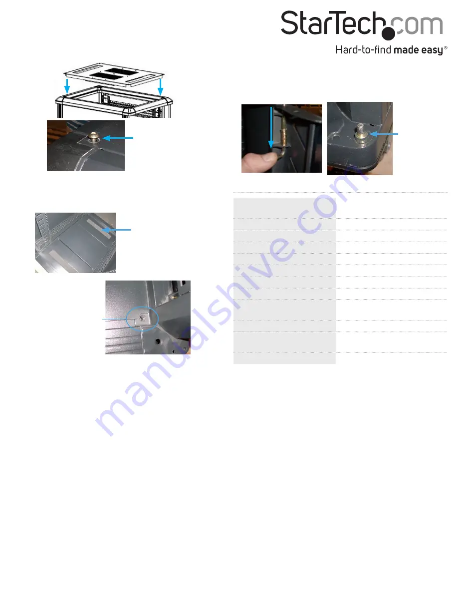
6. To install the front and rear doors, first install the door bearings
into the bottom of the door frames. Install the door onto the
bearing and then pull down the spring loaded door bearing to
install the top of the door.
Door Bearing
Specifications
Description
25U 36” Server Rack Cabinet with
Glass Door
Material
Steel/Aluminum
Color
Black
Maximum Weight Capacity
800 kg
Internal Height
25U
Maximum Mounting Depth
812.8 mm
Mounting Width
19 inches
Mounting Hole Type
Square
External Dimensions
(HxWxD)
1240.4mm x 600.0mm x
900.0mm
Net Weight
72 kg
Standards
EIA RS-310D, IEC297-2, DIN41491
(Part 1)
Certifications
RoHS, WEEE


