57 |
P a g e
OWNER’S
MANUAL
|
STARTRAC 263 4WD
–
8G
–
STAGE
–
V
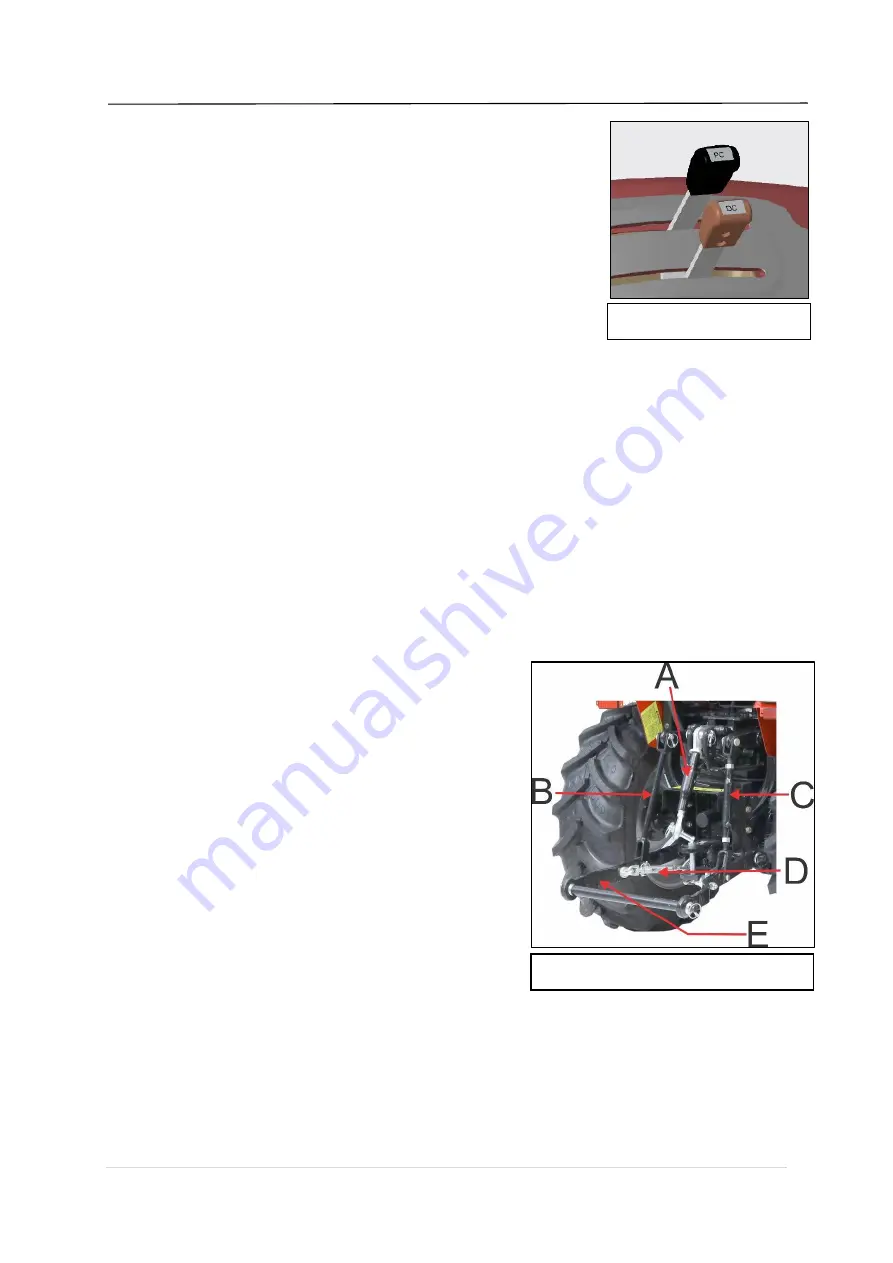
The power-lift control levers are used to set the following modes
• Position lever (Black Color)
• Draft lever (Oran
ge Color)
Each of these modes must be chosen according to the type of
work in hand, the type of implement and the consistency of the
soil.
4.35
POSITION CONTROL (PC) LEVER
•
Position control is used to raise hold and lower three-point
linkage for mounted Implements during tillage/field operation which works above the
ground.
•
Once the height of implement is set, position lever maintains it.
•
Always use Position lever for transporting the implement.
•
One adjustable locking knob is provided for maintaining the specific position.
4.36
DRAFT CONTROL (DC) LEVER
•
Automatic Draft Control is designed to respond at the time of sudden resistance Faced by
the mounted dragging type implements while working in the field.
•
Keep both position and draft Lever (Black & Orange) in lower most position (implement
grounded). Now move the draft lever (Orange) towards upside position on sector as
implement starts rising move back the lever by few mm.
•
Proper Setting of Draft Prevents
: Overloading of engine, breakage of implements, clutch
Slippage, tyre slippage, and excess fuel consumption.
4.37
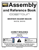
THREE-POINT LINKAGE
Three-point linkage is used to mount the implement,
which is fully mounted, or semi-mounted and used for
different field operation. Three-point linkage is
controlled by hydraulic lever. In these two lower links
are available, of which one side of the lower link is
attached with differential housing and other is used to
hitch the lower pin of the implement. Lift rods are
mounted on lift arm that is operated through rockshaft.
Loose side of Top link is used for attaching upper hitch
pin of implement. Top link is adjustable for proper
setting of implement and ease at the timing of joining.
4.38
ADJUSTABLE TOP LINK
1.
The ADJUSTABLE TOP LINK (A) is supported by a bracket with Two fixing holes.
2.
The correct hole to use depends on the height of the implement.
3.
For length adjustment of top link, fix the top link other end and turn the lever for increasing
or decreasing the length.
4.
Adjust the length of the top link to vary the attachment angle of the implement in relation to
the ground.
Fig.4.21
Fig.4.22
Summary of Contents for 263-4WD-8G-STAGE-V
Page 1: ...OWNER S MANUAL 263 4WD 8G STAGE V OWNER S MANUAL 263 4WD 8G STAGE V EDITION 210312...
Page 3: ...3 P a g e OWNER S MANUAL STARTRAC 263 4WD 8G STAGE V...
Page 5: ...5 P a g e OWNER S MANUAL STARTRAC 263 4WD 8G STAGE V...
Page 37: ...37 P a g e OWNER S MANUAL STARTRAC 263 4WD 8G STAGE V 1 2 3 4...
Page 38: ...38 P a g e OWNER S MANUAL STARTRAC 263 4WD 8G STAGE V 5 7 6...
Page 80: ...80 P a g e OWNER S MANUAL STARTRAC 263 4WD 8G STAGE V 5 65 WIRING CIRCUIT DIAGRAM...


