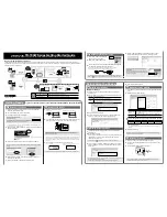
3. Suitable Location for the Installation
The unit's location can be underneath the
front, the seat or the back as shown to
the right. Also remember that there
shouldn't be any metal obstructing the
device view because of the internal
GPS & GSM antennas.
The antennas are located to the right
side of the device when looking at
it from the front, so keep this in mind
when positioning the device inside
the motorcycle.
4. Basic Installation
1. Identify the Power cables in the cable, Red for power (+12VDC or +24VDC)
Black for Ground, White for Ignition & Blue for Panic Button.
2. Connect the wires from the STTCK 5000 to the motorcycle.
a)
Red: Power Source (+12VDC or +24VDC vehicle are supported)
This connection point should be fuse protected to not more
than 5 Amps
b) Black: Ground (Normally on the Vehicle chasis)
c)
White: Ignition detection (Connected to the ignition's key
position that closes the circuit between the battery's positive
voltage and the vehicle's electrical system. Do not connect on
the start position.
Quick Installation Guide
Vehicle ignition switch
Start (4th position)
Run (3rd position)
Accesories (2nd position)
Off
+12 to +24
VDC
GND
White (Ignition)
Blue (Panic Button)
5. Installer Check List.
•
Screw driver kit.
•
Socket wrench set
•
Allen wrenches Metric
•
Fluke Meter (or some kind of VTVM)
•
Utility knife with sharp blades
•
Under dash light
•
Soldering Iron and solder
•
Ratchets and extensions
•
Hot glue gun
•
Crimpers
•
Cutters (assortment)
•
Tie Wrap
•
Tape 3M super 33+
•
Tape 3M super flex
•
Contact cleaner
•
Fuses
To heavy battery wire
GND
d)
Blue(optional): Panic Button (If you want to use this feature put
one terminal of the push button connected to this wire, and the
other one to ground.
Panic Buttton


