17
3.3 WIRING PROCEDURES AND ROUTES
Before making any electrical connections to the machine, selection of wire gauge and wire type is very important.
Any compromise with the wire selection will compromise with the efficiency as well as the safety of the plant.
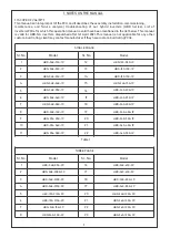
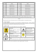
Proper color coding of cables is recommended as per IEC standards throughout the plant. However, the chart
provided is only for assistance and no reference shall be made to it in case of any discrepancy later on.
Follow the procedure in below steps for making electrical connections.
1.
All the connections to this machine are done through bottom cable entry only. Hence, no wires should be
hanging. Proper routing of cables through trench is mandatory.
2. Open the front door and locate the gland plate at the front bottom surface of the machine. The gland plate will
have several glands which can be loosened for cable entry.
3. Route all the cables through the bottom of the machine, through the glands and then into the machine.
4. Ensure too many cables are not clustered around the base or inside of the unit as it may hinder easy opening of
the door when required.
5. Ensure that all the circuit breakers/ MCBs/ MCCBs/ Dis-connectors are in OFF position before any connections
are made.
6. Locate the terminals provided for connecting the incoming cables. All the terminals are of bus bar type with
ring type/ pin type connections. Information about the terminal sizes is part of the technical datasheet provided
during ordering stage.
7. Connections of DC should be made first. In case of DC, always connect the negative first and then connect the
positive side.
8. All cables should be routed through the gland located directly below that terminal. This is recommended for
maintaining clearances between the cables. All the cables should be vertically aligned with their respective
terminals.
9. Use proper stripping and crimping tool for the cable termination. Any loose connections or wrong hardware
sizing issues may lead to lose contacts ultimately leading to fire hazards.
10. Once all the cables have been crimped properly, we can start making connections between the incoming
cables and terminals.
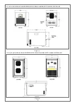
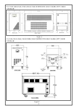
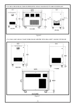
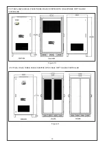
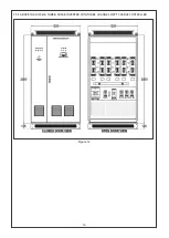
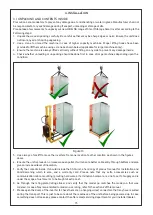
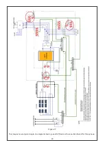
Refer to the figure as per enclosure as to locate the various terminals provided. A common sequence of
terminals is provided in all the machines with same type of numbering.
Always start with battery connections. Locate DC (-) terminal to make connections followed by DC (+)
terminals.
Now connect the PV (-) followed by PV (+) cables. There may be one or three nos. of MPPT chargers depending
upon the capacity of system. In case of multi MPPT charger machine, repeat PV connection for all 3 MPPT
sections.
Connect the AC Line and neutral terminals now. In case of three-phase systems, ensure proper phase
sequence is followed. Neutral should always be connected to Neutral terminal only.
Lastly, connect the load terminals in proper sequence.
Neutral of Grid and Neutral of Loads is connected to a common point to maintain the continuity of Neutral under
all circumstances.
11. Use proper nut/ bolts/ washers for connecting the cables to the Terminals provided in the machine. Please be
noted that use hardware of recommended sizes only. Proper contact is required between the cable, cable lugs
and the terminals. Any issues may lead to heating of contacts ultimately leading to fire hazards.
12. All terminals provided are of copper material only. Hence lugs used should be of copper only for homogeneity
of contact. In case of Aluminium cable, bimetallic lugs are mandatory.
13. Use proper spanners to tighten the nut/ bolts. Ensure that once tightened, all the lugs should be vertical. The
conductors are carrying high currents and voltages; hence clearances between them should be maintained.
14. Double check all the connections for polarity and type to avoid any malfunction later on.
15. Double check the tightness of all the nut and bolts.
16. It is recommended to route AC and DC cables with some minimum clearances in between.

