24
HOW TO IMPLEMENT OPERATIONS USING DISPLAY KEYPAD UNIT
All the operations, settings change and parameter viewing on display are performed using pushbuttons or a
combination of pushbuttons. In this section, we describe some of the events that can be performed using the
pushbutton keys provided on the DKU. Some of these operations include:
Date and Time settings
Scrolling through the various screens
Turning ON and Turn OFF the inverter unit
Resetting the unit in case of fault occurrence
Change of settings
5.3 DATE AND TIME SETTINGS
To set date and time press MODE/ACK button for 10sec. A new window will be opened. Then use Mode/ACK to
move next and +/- to increment and decrement. Now set the date, time, year, and hour, minute and second
one by one and then accept the changes using RESET button until the display starts showing the Home Page
or the Mimic page. These settings can also be changed using the Test Software only if you have been
authorized or trained with its usage.
5.4 SCROLLING PAGES
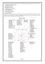
There are a total of 12 standard display screens of the DKU displaying the various parameters of the machine.
These pages have been segregated in a manner such that all the similar parameters have been displayed on a
single page.
The active screen can be changed by pressing the MODE key to advance a screen and the BACK key to go back a
screen. We would now explain each of the screens in details along with all the fields on any of the screen and how
to toggle between various parameters on a single screen. We would start from the HOME PAGE or the MIMIC
PAGE:
5.4.1 HOME PAGE
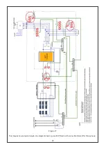
Home Page/ Mimic Page is the first page that appears after booting up of the system. It basically consists of a
Mimic Single Line Diagram along with a few text lines below it.
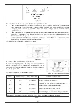
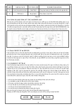
The Mimic shows the basic circuitry and its various elements. There are arrows and dashed lines to show which of
the Power sources is being used at any moment of time. On the DC side there are PV and Battery and depending
upon the usage of these, arrows keep charging direction. On the AC side, there are 2 relay contacts near the Grid
and the inverter output. So, the status of one of the lines shows whether the grid supply connected is available/
being used or not. The second arrow on the inverter output side disappears only when the inverter is faulty, and
loads are bypassed to the grid supply (if available). The detailing of the Mimic diagram has been explained in detail
in the image below:
Figure 19

