42
APPENDIX-2 : HOW TO SELECT OPERATING MODE OF YOUR CHOICE
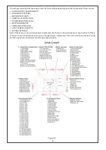
In Section 7 of this manual, we have discussed in detail about the various OPERATING MODES available in Hybrid
Inverters and their working. The three operating modes namely STANDALONE, HYBRID and HYBRID WITH
EXPORT have their own advantages and disadvantages. Hence, each of them should be duly considered before
setting.
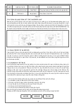
S. No.
DISPLAY FAULT
MEANS
CAUSE
ACTION
18
System Offline
Communic
ation card
/CAN
communic
ation
issue.
The Inverter controller is not
communicating with the
supervisory system.
42. At first need to restart the
inverter once then check.
43. Contact to our technical
personnel.
Table 15
APPENDIX-3 : PV MODULE ARRAY SERIES-PARALLEL ARRANGEMENT
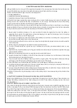
Hybrid Inverter machines are basically DC coupled Solar inverters which have an inbuilt but separate MPPT
solar Charger between the PV and the Battery. This Solar MPPT charger is of Buck type which strictly means
that PV power will be extracted only when the PV voltage is higher than the battery voltage at that instant.
Hence, the series parallel arrangement becomes very important for proper functioning and best generation
results.
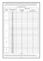
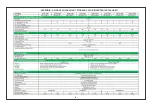
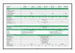
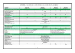
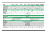
So, before we present the PV sizing chart, we would like to highlight a few points about the series-parallel
arrangement of PV modules.
1. Always keep information handy about the PV module you are going to use. This includes: Open-Circuit Voltage
(Voc), MPPT Voltage (Vmp), Short-Circuit Current (Isc), MPPT Current (Imp), Module Power (Pmp) and no. of
cells in PV module used.
2. Always refer the Inverter datasheet while designing the series parallel arrangement. The parameters o
f importance include:
PV Nominal Capacity (Total)
No of MPPT Channels
Per Channel PV Capacity (Nominal/ Peak)
Max. Open Circuit PV Volts (Voc)
MPPT Voltage Range
PV Minimum Voltage
Max I/P Amps per channel
3. More are the number of modules in series, higher is the plant efficiency and higher is the generation from PV
modules. But there is a limit to maximum number of modules mentioned in the inverter datasheet.
4. Never exceed the Max. Open circuit Voltage permitted by the inverter datasheet. This value is mentioned as
Max. Open circuit PV Volts (Voc) in the inverter datasheet
5. Open circuit voltage of PV module increases in cold season due to module characteristics and hence always
keep a margin between the System Voc and permissible Voc mentioned in the datasheet.
6. The number of strings in parallel should always be kept as low as possible. Also, the summation of all the
string currents should always be less than the Max I/P amps per channel mentioned in the datasheet of
inverter.
7. In case of multi MPPT channel designs (above 50KVA generally) distribute the no of modules equally among
all the 3 MPPT channels for better generation.
8. In case of multi MPPT channels ensure 3 separate PV fields are made. That is, do not combine all the PV
modules in a single AJB and then bring 3 separate set of cables for 3 MPPT chargers in Multi MPPT inverters.
This will hamper the PV generation as MPPT function will not take place at all.


