background image

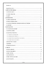
5.2 WORKING OF SYSTEM...............


................................................................................................................................


20


5.3 LOAD CHART & BATTERY SIZING


...........................................................................................................................


21


6. MAINTENANCE & TROUBLESHOOTING


......................................................................................22

6.1 VISUAL INSPECTION........................


...........................................................................................................................


22


6.1.1 CLEANING THE INVERTER EXTERNALLY


...........................................................................................................


22


6.1.2 BATTERY MAINTENANCE........................................................................................................................................


22


6.1.3 PV MAINTENANCE.........................................


...........................................................................................................


22


6.2 TROUBLESHOOTING........................................


...........................................................................................................


22


APPENDIX-1.............................................................................................................................................


25

GENERAL FAULTS AND THEIR SOLUTIONS...


...........................................................................................................


25


A.     INVERTER OUTPUT VOLTAGE IS NOT AVAILABLE


..........................................................................................


25


B.    SOLAR CHARGING IS NOT AVAILABLE...............................................................................................................


25


C.    MAINS CHARGING IS NOT HAPPENING..............................................................................................................


25


D.    OUTPUT FLUCTUATION.............................................................................................................................................


25


APPENDIX-2............................................................................................................................................


26

TECHNICAL SPECIFICATION -LOW VOLTAGE 1-8KVA.............................................................................................


26


APPENDIX-3............................................................................................................................................


28

WARRANTY...........................................................................................................................................................................


28


APPENDIX-4............................................................................................................................................


30

SERVICE AND CUSTOMER CARE...................................................................................................................................


30


2 of 30

Copyright Declaration

The copyright of this manual exclusively belongs to STATCON ENERGIAA PVT. LTD. Any corporation of individual 
should not plagiarize, partially copy or fully copy (including software, etc.) it. Reproduction or distribution of it any 
from or by any means is not permitted. All rights reserved. STATCON ENERGIAA PVT. LTD. Reserves the right of 
final interpretation. This document is subject to changes without prior notice. This is valid only for SEOG MPPT-
based PCUs and not for custom built ratings.

TECHNICAL SPECIFICATION -HIGH VOLTAGE 5-15KVA..........................................................................................


27


5. OPERATING MODES AND LOAD CHART


.....................................................................................


19


5.1 DETAILS OF PRIORITY MODES


................................................................................................................................


19


Summary of Contents for SEOG Series

Page 1: ...Optional two way IoT access STATCON Inspire Innovate Implement ENERGIAA...

Page 2: ...ING 12 3 2 ELECTRICAL CONNECTION 13 3 2 1 CONNECTION TO THE BATTERY 13 3 2 2 CONNECTION TO AC SUPPLY IN 13 3 2 3 CONNECTION OF SOLAR MODULES PV SOLAR IN 13 3 2 4 CONNECTION OF LOAD LOAD OUT 13 3 3 INS...

Page 3: ...NDIX 3 28 WARRANTY 28 APPENDIX 4 30 SERVICE AND CUSTOMER CARE 30 2 of 30 Copyright Declaration The copyright of this manual exclusively belongs to STATCON ENERGIAA PVT LTD Any corporation of individua...

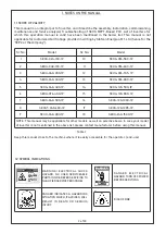
Page 4: ...48 4K0 1P 14 SEOG 120 5K0 1P 6 SEOG 096 4K0 1P 15 SEOG 120 8K0 1P 7 SEOG 048 5K0 1P 16 SEOG 120 10K0 1P 8 SEOGT 048 6K0 1P 17 SEOG 120 12K5 1P 9 SEOG 048 8K0 1P 18 SEOG 240 15K0 1P NOTE This manual ma...

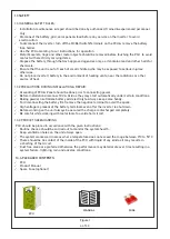
Page 5: ...anel should be done prior to connecting power Before installation disconnect PV Grid as they may start automatically under certain conditions Baking powder neutralizes battery acid electrolyte Always...

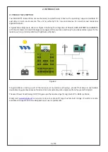
Page 6: ...rces selectively to provide seamless power to the loads so as to incur minimum bills with optimum utilization 2 1 PRODUCT DESCRIPTION Congratulations on being a part of the Indian solar revolution and...

Page 7: ...nections to unit are made from the bottom end at rear side The terminology and sequence of terminals have been kept the same for as many models as possible for ease of understanding and has been expla...

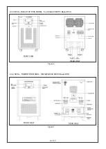
Page 8: ...7 of 30 2 3 1 SEOG TABLE TOP TYPE MODEL 0 5 1 KVA 24V 48V MPPT Based PCU Figure 4 FRONT VIEW REAR VIEW 2 3 2 SEOG TOWER TYPE MODEL 2 4 KVA 48V MPPT Based PCU Figure 5 FRONT VIEW REAR VIEW...

Page 9: ...8 of 30 2 3 3 SEOG TABLE TOP TYPE MODEL 5 6 KVA 48V MPPT Based PCU Figure 6 FRONT VIEW REAR VIEW 2 3 4 SEOG TOWER TYPE MODEL 10KVA 96 120V MPPT Based PCU Figure 7 FRONT VIEW REAR VIEW...

Page 10: ...MONITORING Largest LCD display in its class for great visuals Inbuilt data logging capability up to 5 years optional RS 232 RS 485 GPRS remote monitoring available optional 2 4 3 INDUSTRIAL GRADE INV...

Page 11: ...battery to PCU should be kept to minimum to avoid the losses Cable sizing should also be done keeping in mind to minimum the losses 3 0 3 PV Place the solar panels PV in the direction of maximum durat...

Page 12: ...This image shows a typical single line diagram showing use of SPD and earth connection there of 11 of 30...

Page 13: ...BLE LUG SIZE CHART AS PER IS 3961 PART V THIMBLE LUG DIA AT SCREW SIDE IS 6 2 MM THIMBLE LUG size should be same as wire size given below Table 3 ENSURE THAT ALL THE MCB s ARE IN OFF POSITION BEFORE S...

Page 14: ...be connected to the PV screw terminals of PCU Connect the ve terminal of the PV output to the PV terminal of PCU Connect the ve terminal of the PV output to the PV terminal of PCU Follow the wire siz...

Page 15: ...e from house to clamp It is advisable to have a proper earthing near your house or solare panels Please ensure that earth connection of SPD as per section 3 0 4 above is as drawing 3 5 STARTING UP THE...

Page 16: ...H DATE BATT V TIME INC INC INC BATTERY Voltage Charging Current Discharging Current Temperature PV PV Voltage PV Current PV Power PV Today s kWH INVERTER Voltage Current Frequency Load kVA GRID Voltag...

Page 17: ...e g 48 4 kVA Press key INC to select your battery type LM VRLA NI CAD Now press key SET to select battery capacity Ah Using INC DEC keys we can change battery capacity Now press SET key to choose pri...

Page 18: ...WILL START GLOWING WHICH INDICATES INVERTER IS SWITCHED ON LED OF CHARGING SOURCE WILL KEEP BLINKING DURING CHARGING 4 5 MENU SETTING FLOW CHART Figure 14 Disclaimer Due to technical innovations LCD...

Page 19: ...AULT as a prefix with each fault number The lists of fault name are given in the Table 4 as per their respective fault number codes FAULT INTERPRETATION FAULT CODE IN DISPLAY SYSTEM TRIP FAULT 0 INVER...

Page 20: ...0 then AC loads switch to grid source if grid supply available This mode allows the battery charging through grid when battery discharge more than 80 MODE 4 S G B Suitable for areas where grid supply...

Page 21: ...PV POWER AC LOAD POWER NOMINAL VOLTAGE PV POWER AC LOAD POWER NOMINAL VOLTAGE PV POWER AC LOAD POWER NOMINAL VOLTAGE NOMINAL VOLTAGE NOMINAL VOLTAGE NEITHER CHARGE NOT DISCHARGE NOMINAL VOLTAGE DISCHA...

Page 22: ...QTY TOTAL WATTS QTY TOTAL WATTS QTY TOTAL WATTS LOADS 15W 3 45 6 90 12 180 15 225 40W 1 40 3 120 6 240 10 400 60W 2 120 4 240 8 480 12 720 150W 1 150 2 300 3 450 4 600 250W 1 250 1 250 1 250 2 500 35...

Page 23: ...storm or a long utility outage cycling to a discharge level of 80 is acceptable Totally discharging a battery may result in permanent damage and reduced life Our PCUs limit the depth of discharge to 6...

Page 24: ...CASE OF ANY OTHER REASON CONTACT TO SERVICE ENGINEER FAULT 5 SYSTEM OVER TEMPERATURE This fault occurs due to overheating of PCU than its nominal range It may be due to fan failure or improper ventil...

Page 25: ...attery terminals REMEDY Check the battery voltage and battery connections IN CASE OF ANY OTHER ISSUE CONTACT TO SERVICE ENGINEER FAULT B MAINS UNDER FREQUENCY This fault may occur due to improper freq...

Page 26: ...f PV MCB and keep it at ON position ON OFF switch is kept in OFF position Check the position of ON OFF switch and keep it at ON position PV is connected in reverse polarity Check the PV connection pol...

Page 27: ...26 of 30 APPENDIX 2 TECHNICAL SPECIFICATIONS...

Page 28: ...27 of 30...

Page 29: ...warranty will stand null and void For a warranty claim to be valid the warranty card of the respective product bearing the date of manufacturing purchase must be fully legible and the end customer inv...

Page 30: ...t is mandatory that said PCU is stored kept under use a dust free and covered area with free airflow available It is not designed for use in open under the sun unless very specifically deigned manual...

Page 31: ...servicing customer support in one of the following ways 1 Email us at servicing energiaa in 2 Call us at 1800 891 3319 toll free 3 Message us on Energiaa Care WhatsApp 91 9821396421 4 Scan the QR Cod...

Page 32: ...B 81 Sector 63 Noida G B Nagar 201307 U P INDIA Phone 91 120 4088665 4258645 Toll Free 1800 891 3319 Website www energiaa in E mail info energiaa in...

Reviews: