Connect a compressed air line to the filter/regulator assembly at the back of the unit.
• Install (1) 3/8” NPT Male x Female Elbow (shipped loose with PT Cube) into the 3/8” NPT
Female port of the filter regulator, oriented up, down or rear-facing as desired after tightening
with a wrench. Be sure to use Teflon tape to prevent leaks.
• Install (1) 3/8” NPT Male x 1/4” Industrial Quick-Disconnect Fitting (shipped loose with PT
Cube) into the Female port of the elbow, then tighten with a wrench. Be sure to use Teflon
tape to prevent leaks.
NOTE: you can plumb straight into the filter/regulator port if you prefer
• Use clean, CDA (Clean, dry air) as the air supply. Check that a dryer and filter are attached to the
air equipment you are going to use, and if not attached, attach them.
• Check that the compressor has the following flow rates and use a compressor that has sufficient
leeway.
• This system has a regulator with filtration installed on the back of the main unit for control
of pressure (psi) used to clean your parts
•
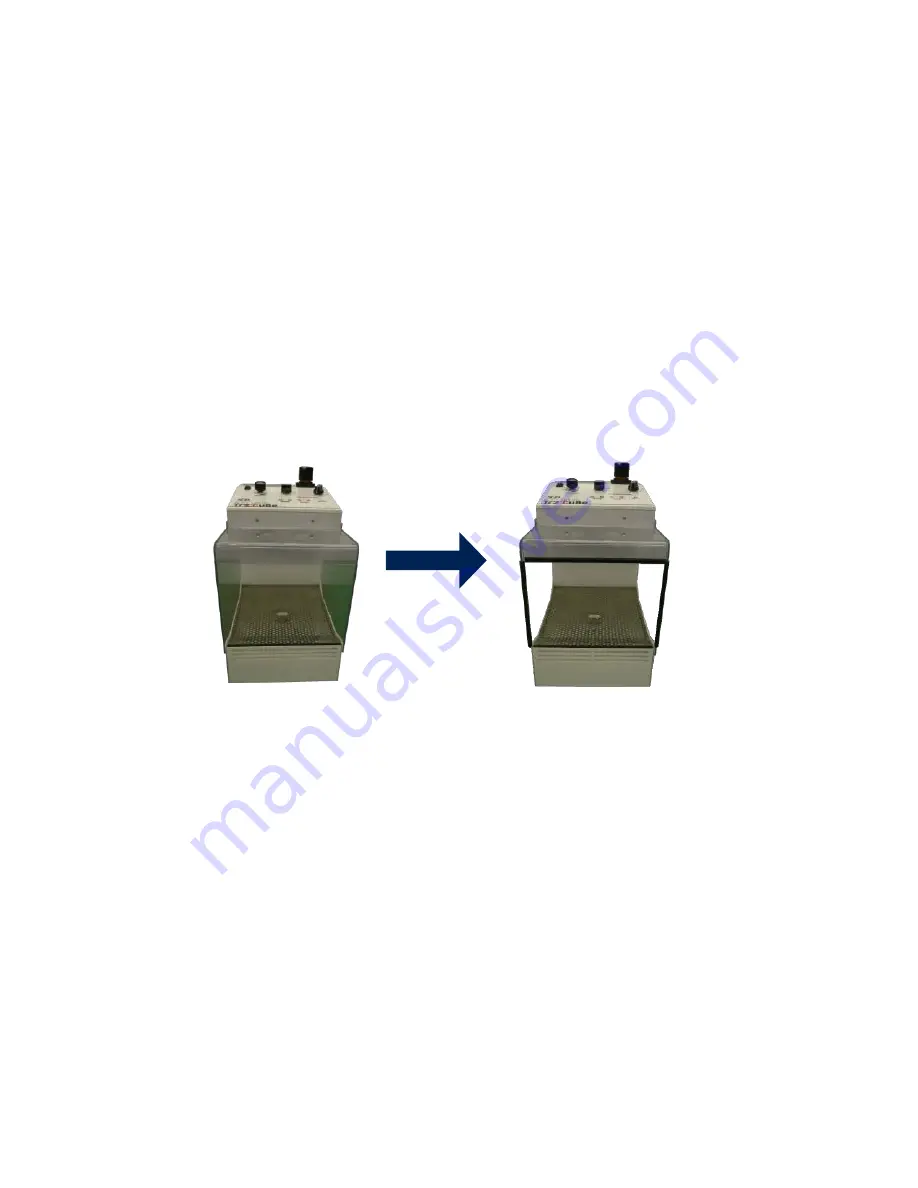
6-4 Attaching the Work Inlet Cover
• Work inlet covers are included for preventing scratching when a work piece hits
• the work inlet of the device. Attach and use them as appropriate.
• Two types of black work inlet cover of different lengths (one long and one short) are provided.
Fasten them at the attachment positions corresponding to their lengths.
• The work inlet covers are held between resin plates, but if these come off during use, reaffix
them using adhesive glue (supplied separately).
*Attach the work inlet cover to the transparent resin portion of the main unit inlet.
Prior to cover attachment
After attaching the cover
7. Operation
7-1 Procedure When Starting Operation
①Install the device in a location with a flat top and carry out wiring and air connection.
②Open the compressor valve and supply air to the device. Operate the air equipment installed outside
the device to adjust the air pressure supplied to the device. (between 29 psi and 87 psi).
③Turn the power switch of the device on, check that the ‘IONIZER’ - ‘Ready’ lamp on the main unit display
panel is on, and insert a work piece. The sensor will detect the work piece and operation will begin.
• There is a warm up time of about 5 seconds from when the power switch of the
• device is switched on, during which time all of the lamps in the display panel of the main unit are
illuminated.
• The fan runs when the power switch of the device is switched on.
• When blowing, the ‘Working’ lamp is illuminated in conjunction with the blow
• pulse. The ionizer also works in conjunction with the blow and runs until 3 seconds after the blow is
turned off. The ‘RUN’ lamp is illuminated while the ionizer is running.
④ Adjust the fan speed, pressure, time and pulse of the system to optimize cleaning based on the amount of
particles attached to the work piece.
• Although the device has a built in photoelectric sensor, it also has ‘Time’ settings for blowing continuously
for 3 seconds, 5 seconds, 10 seconds, and 15 seconds after the sensor activates once, for when work
detection is difficult due to the work material (transparent work pieces etc.) or you want to manage the
blow time. Configure these settings accordingly.
• When the fan speed setting is fast, the suction capability increases greatly, and the operating noise
becomes correspondingly loud. The recommended setting is within the blue zone of the fan speed knob.
Sufficient suction power also is exhibited with the main unit Air pressure gauge reading at 87 psi.
5


