D2605-01-02
5~USER CONFIGURATION (continued).
1. NFC - The Symbol is on when a NFC field is detected. When a detected field is lost the symbol
will turn off after a few seconds.
2. TRANSMIT/RECEIVE: Symbol on when either NFC or USB communication is active.
3. USB: Symbol on when USB port is connected to a PC. Please note battery is not required during
configuration.
4. LOG: Not used
5. Not used
6. BAR GRAPH: Indicates the state of the logger. The condition is dependent on the selected
logger mode, either Single or Rolling mode.
Single Mode (Log to the maximum number of logs then stop)
Start of Log Mid Log End of Log (alternating)
Rolling Mode (Log to the maximum number of logs then as each new log is taken the oldest log is
discarded)
Start of Log Mid Log Rolled over Log (max bar toggles)
7. DEG: Degree symbol “°” used to indicate either °C or °F on the last digit.
8. DIGITS: Six-digit 14 segment display with – sign, range 9999.9 to -9999.9. Advanced mode
offers two temperature-dependent 32-character message options.
9. WARNING ICON: This symbol will toggle on and off to indicate a warning. The warning symbol
will be active either when the sensor signal is out of range, not connected or when the battery is low.
!
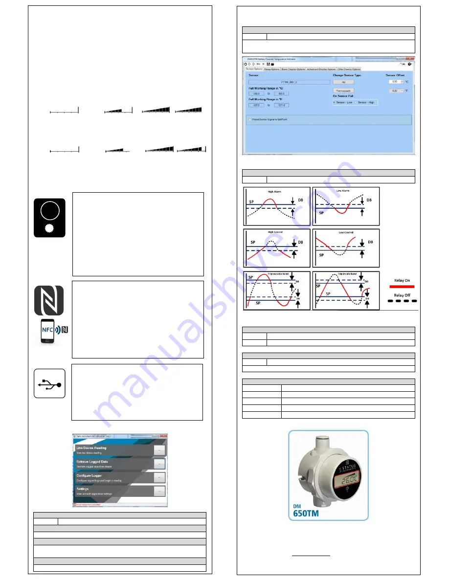
USBSLogLink CONFIGURATION SOFTWARE
LIVE DEVICE READING TAB
Display
Live temperature value
RETRIEVE LOGGED DATA TAB
Download and graph recorded logged data
CONFIGURE LOGGER
Set new log (rolling or fixed), interval time, number of logs, delay start
Enter (tag and contact), reset (max and min) Sync clock
SETTINGS
Save log location, °C, °F
5~USER CONFIGURATION (continued).
USBSpeedLink CONFIGURATION SOFTWARE
SENSOR TAB
Select
Input type, sensor off-set
Pre-set Sensor Signal to Set-Point the input value can be fixed to a pre-
determined value, the messaging display and relay will respond accordingly.
DM650TM configuration software (Sensor Options Tab).
RELAY OPTIONS TAB
Select
Select relay operation, set -point, dead band, relay name
BASIC DISPLAY OPTIONS TAB
Select
Display units, resolution, Zero set-point
Select
LED Options for battery, relay
ADVANCED DISPLAY OPTIONS TAB
Select
Message bands, custom messages
Use this software tab to set up advanced scrolling user messaging
OTHER DEVICE OPTIONS TAB
Enter
Tag, contact details
Enter
Android passkey (protect logged data)
Enter
Device location
Read/clear
Maximum and minimum reading
Synchronise
Clock
This document is subject to change without notice. No responsibility is taken for errors.
Status Instruments Ltd, Status Business Park, Gannaway Lane, Tewkesbury,
Gloucestershire, UK, GL20 8FD
Web Page: www.status.co.uk, Email: sales@status.co.uk
Technical Support: support@status.co.uk
Tel: +44 (0) 1684 296818, Fax: +44 (0) 1684 293746
MULTIFUNCTION ALERT LED
The alert LED normal state is off, on alert the LED will emit a intense
white light pulse every 5 seconds. The LED can be programmed to
pulse on any of the following combined events:
Mode
Description
No events The LED never operates, extending battery life.
(Factory default setting)
Battery
Alert on low battery detect.
Trip
Alert when relay 1 trip is on.
Temperature In advanced mode only the alert LED can be made to
alert in any one of eight user-set temperature bands. Example, to
alert operator when temperature is outside a safe operating range.
The function of the alert LED can be further enhanced with the option
of displaying an alert message in advanced display mode.
NFC LOGGER INTERFACE
The NFC interface allows the instrument to communicate with an
Android device using NFC connectivity.
The prime function of the interface is to read logged data from the
device using a free app, which is available for downloading to
Android devices.
The app allows the user to read existing logs, change the log
manifest, start a new log, synchronise the instrument clock and reset
the maximum/minimum/average readings. Logs can run to a fixed
number and stop or continually roll over, up to 5000 log points can be
recorded. The start of the log can be delayed up to one month.
Note: For larger logs the data may take over a minute to fully
download via the NFC interface.
USB LOGGER INTERFACE (connector inside housing)
The USB interface allows the instrument to communicate with a PC
running the USBLogLink software
The prime function of the interface is to read logged data from the
device using free software available to download.
The software allows the user to read existing logs, change the log
manifest, start a new log, synchronise the instrument clock and reset
the maximum/minimum readings.
USBLogLink is available from the manufacturer or supplier.


