Chapter 1 – Description
D18326204C - 11/2004
11
1.2.
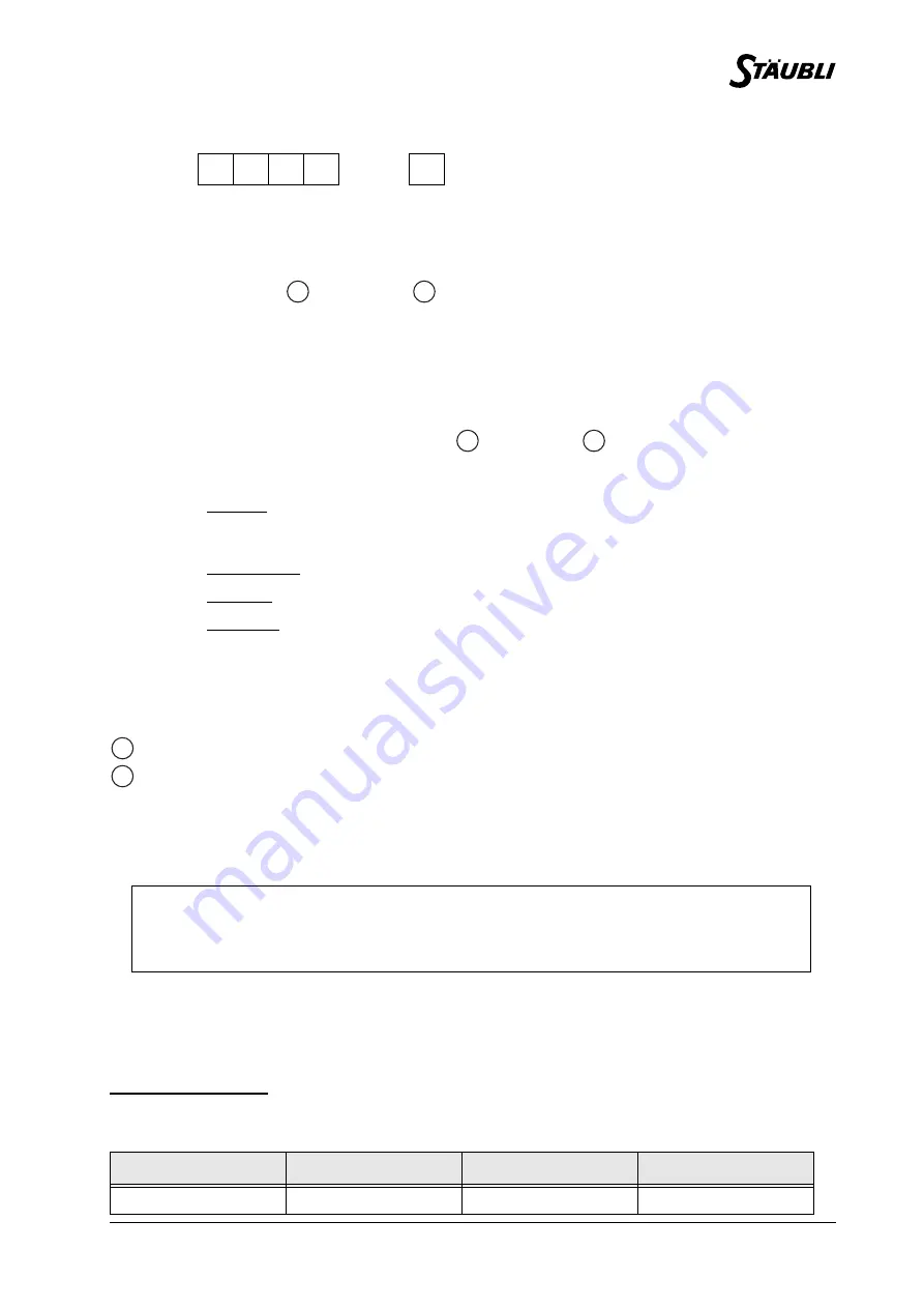
DESIGNATION OF ROBOTS OF THE RX SERIES 90B FAMILY
1.3.
GENERAL CHARACTERISTICS
1.3.1. OVERALL DIMENSIONS
(figures 1.2 and 1.3)
Vertical cable outlet
Horizontal cable outlet
1.3.2. WORK ENVIRONMENT
• Working temperature: + 5°C to + 40°C (according to standard(s) and/or directive(s): NF EN 60 204
-
1)
• Humidity: 30% to 95% max. non-condensing (according to standard(s) and/or directive(s): NF EN 60
204
-
1)
• Altitude: 2000 m max
• Vibrations: please consult us
Clean room application: Cleanliness class ISO 4 according to standard ISO 14644-1
1.3.3. WEIGHT
RX
9
0
B
CR
(1) (2) (3) (4)
(5)
(1)
RX family arm
(2)
Maximum reach between joints 2 and 5 expressed in decimeters:
dimension
+ dimension
(3)
Number of active joints:
• 0 = 6 active joints.
• 5 = 5 active joints, geometry being conserved.
(4)
RX family changed to "B".
(5)
Upper case letters to indicate an option.
• L = extended forearm: dimension
+ dimension
(figure 1.3).
• CR = clean room application.
These letters can be combined.
Example: LCR = extended forearm clean room application.
In the manual, the following terminology is used:
Standard arm: for arm with standard geometry
(figure 1.2).
Long arm: for arm with different geometry where forearm is extended
(figure 1.3).
5-joint arm: for arm with 5 active joints.
CAUTION:
It may be necessary to perform a warm-up cycle before nominal performances are
obtained.
STANDARD ARM
LONG ARM
5-JOINT ARM
LONG 5-JOINT ARM
111 kg
113 kg
106 kg
107 kg
A
B
A
C
1
2
Summary of Contents for 90B family
Page 1: ...St ubli Faverges 2004 Arm RX series 90B family Characteristics D18326204C 11 2004...
Page 4: ...4 D18326204C 11 2004...
Page 6: ...6 D18326204C 11 2004...
Page 7: ...Chapter 1 Description D18326204C 11 2004 7 CHAPTER 1 DESCRIPTION...
Page 8: ...8 D18326204C 11 2004 Figure 1 1 B A C D E F 3 4 5 2 1 6 RX 90 RX 90 R...
Page 10: ...10 D18326204C 11 2004 Figure 1 2 Figure 1 3...
Page 12: ...12 D18326204C 11 2004 Figure 1 4...
Page 14: ...14 D18326204C 11 2004 Figure 1 5...
Page 16: ...16 D18326204C 11 2004 Figure 1 6 Effective tapped depth 8 mm...
Page 18: ...18 D18326204C 11 2004 Figure 1 7 Figure 1 8 Figure 1 9 Figure 1 10...
Page 22: ...22 D18326204C 11 2004 Figure 1 13...
Page 24: ...24 D18326204C 11 2004 Figure 1 14...
Page 26: ...26 D18326204C 11 2004 Figure 1 15 Figure 1 16 11 1...
Page 30: ...30 D18326204C 11 2004...
Page 31: ...Chapter 2 On site preparation D18326204C 11 2004 31 CHAPTER 2 ON SITE PREPARATION...
Page 32: ...32 D18326204C 11 2004 Figure 2 1...
Page 34: ...34 D18326204C 11 2004...
Page 35: ...Chapter 3 Installation D18326204C 11 2004 35 CHAPTER 3 INSTALLATION...
Page 36: ...36 D18326204C 11 2004 Figure 3 1 Figure 3 2 Figure 3 3 1 5 X L Y 2 P 7 H 6 3 4...
Page 38: ...38 D18326204C 11 2004 Figure 3 4 Figure 3 5 Figure 3 6 Figure 3 7 6 3 5 7 3...
Page 42: ...42 D18326204C 11 2004...


