Chapter 1 – Description
D18326204C - 11/2004
13
1.4.
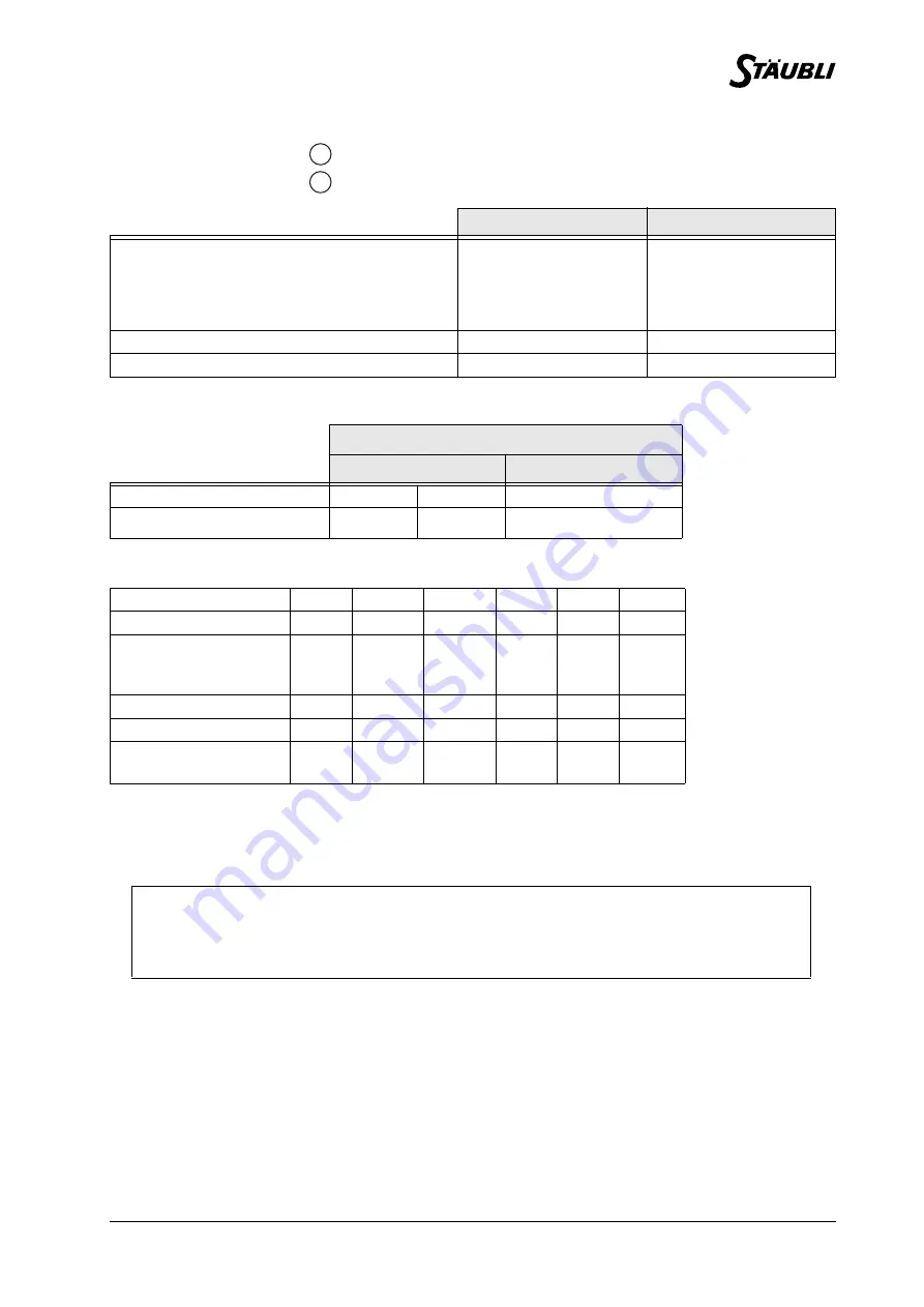
PERFORMANCE
1.4.1. TORQUE LIMITS
1.4.2. AMPLITUDE, SPEED AND RESOLUTION
Low speed for manual control pendant:
• cartesian mode 250 mm/s
• revolute mode: 10% of nominal speeds
Maximum Cartesian speed: 2 m/s
1.4.3. MODIFICATION OF AMPLITUDES
The arm is installed to obtain maximum angular amplitudes.
The amplitude of the joints can be voluntarily limited by the "software" (see chapter on programming). Also,
the position of the mechanical travel limiters on joints 1, 2 and 3 and of the electrical travel limiters on joints
1 and 2 can be modified in a certain number of positions (for modification, please consult STÄUBLI).
See
figure
Brake release access area
Area accessible in righty configuration
STANDARD ARM
LONG ARM
Work envelope
R.M max. reach between joints 2 and 5
900 mm
1100 mm
R.m min. reach between joints 2 and 5
289 mm
401 mm
R.b reach between joints 3 and 5
450 mm
650 mm
Maximum speed
at load center of gravity
11 m/s
12.6 m/s
Repeatability
at constant temperature
± 0.02 mm
± 0.025 mm
REFERENCE JOINT
JOINT 5 (Z
6
)
JOINT 6 (Z
7
)
Static torque (Nm)
24
(1)
14
(2)
10
(1) if joint 6 torque = 0
(2) for maximum torque
on joint 6
Peak torque (Nm)
100
(1)
57
(2)
43
Joint
1
2
3
4
(1)
5
6
(1) For 5-joint arms, joint
4 is fixed. Joint 5
corresponds to joint
4 and joint 6 to joint 5
of the software.
(2) Multiturn version
available as an
option.
(3) without axis 5
interaction.
Amplitude (°)
320
275
285
540
225
540
(2)
Working range
distribution (°)
A
± 160
B
± 137.5
C
± 142.5
D
± 270
E
+120
-105
F
± 270
Nominal speed (°/s)
236
200
286
401
320
580
Maximum speed (°/s)
356
356
296
409
800
1125
(3)
Angular resolution
(°.10
-
3
)
0.87
0.87
0.72
1
1.95
2.75
CAUTION:
In some arm configurations, the maximum joint speeds can be reached only if payloads
and inertias are reduced.
1
2
Summary of Contents for 90B family
Page 1: ...St ubli Faverges 2004 Arm RX series 90B family Characteristics D18326204C 11 2004...
Page 4: ...4 D18326204C 11 2004...
Page 6: ...6 D18326204C 11 2004...
Page 7: ...Chapter 1 Description D18326204C 11 2004 7 CHAPTER 1 DESCRIPTION...
Page 8: ...8 D18326204C 11 2004 Figure 1 1 B A C D E F 3 4 5 2 1 6 RX 90 RX 90 R...
Page 10: ...10 D18326204C 11 2004 Figure 1 2 Figure 1 3...
Page 12: ...12 D18326204C 11 2004 Figure 1 4...
Page 14: ...14 D18326204C 11 2004 Figure 1 5...
Page 16: ...16 D18326204C 11 2004 Figure 1 6 Effective tapped depth 8 mm...
Page 18: ...18 D18326204C 11 2004 Figure 1 7 Figure 1 8 Figure 1 9 Figure 1 10...
Page 22: ...22 D18326204C 11 2004 Figure 1 13...
Page 24: ...24 D18326204C 11 2004 Figure 1 14...
Page 26: ...26 D18326204C 11 2004 Figure 1 15 Figure 1 16 11 1...
Page 30: ...30 D18326204C 11 2004...
Page 31: ...Chapter 2 On site preparation D18326204C 11 2004 31 CHAPTER 2 ON SITE PREPARATION...
Page 32: ...32 D18326204C 11 2004 Figure 2 1...
Page 34: ...34 D18326204C 11 2004...
Page 35: ...Chapter 3 Installation D18326204C 11 2004 35 CHAPTER 3 INSTALLATION...
Page 36: ...36 D18326204C 11 2004 Figure 3 1 Figure 3 2 Figure 3 3 1 5 X L Y 2 P 7 H 6 3 4...
Page 38: ...38 D18326204C 11 2004 Figure 3 4 Figure 3 5 Figure 3 6 Figure 3 7 6 3 5 7 3...
Page 42: ...42 D18326204C 11 2004...


