background image

3 / 24


Sicherheitshinweise

Safety instructions

Die Montage und Installation der Produkte darf ausschließlich 

durch Elektrofachkräfte oder elektrotechnisch unterwiesene Per-

sonen unter Berücksichtigung aller anwendbaren gesetzlichen 

Sicherheitsbestimmungen und Regelungen erfolgen�

Stäubli Electrical Connectors (Stäubli) lehnt jegliche Haftung infol-

ge Nichteinhaltung dieser Warnhinweise ab�

The products may be assembled and installed by electrically 

skilled or instructed persons duly observing all applicable safety 

regulations�

Stäubli Electrical Connectors (Stäubli) does not accept any liabil-

ity in the event of failure to observe these warnings�

Benutzen Sie nur die von Stäubli angegebenen Einzelteile und 

Werkzeuge� Weichen Sie nicht von den hier beschriebenen 

Vorgängen zur Vorbereitung und Montage ab, da sonst bei der 

Selbstkonfektionierung weder die Sicherheit noch die Einhaltung 

der technischen Daten gewährleistet ist� Ändern Sie das Produkt 

in keiner Weise ab�

Use only the components and tools specified by Stäubli� In case 

of self-assembly, do not deviate from the preparation and assem-

bly instructions as stated herein, otherwise Stäubli cannot give 

any guarantee as to safety or conformity with the technical data� 

Do not modify the product in any way�

Nicht von Stäubli hergestellte Steckverbindungen, die mit Stäubli-

Elementen steckbar sind und von einigen Herstellern manchmal 

auch als „Stäubli-kompatibel“ bezeichnet werden, entsprechen 

nicht den Anforderungen für eine sichere, langzeitstabile elekt-

rische Verbindung und dürfen aus Sicherheitsgründen nicht mit 

Stäubli-Elementen gesteckt werden� Stäubli übernimmt daher 

keine Haftung, falls diese von Stäubli nicht freigegebenen Steck-

verbindungen mit Stäubli-Elementen gesteckt werden und des-

halb Schäden entstehen� 

Connectors not originally manufactured by Stäubli which can be 

mated with Stäubli elements and in some cases are even de-

scribed as ”Stäubli-compatible” by certain manufacturers do not 

conform to the requirements for safe electrical connection with 

long-term stability, and for safety reasons must not be plugged 

together with Stäubli elements� Stäubli  therefore does not ac-

cept any liability for any damages resulting from mating such 

connectors (i�e� lacking Stäubli approval) with Stäubli elements� 

   Caution, risk of electric shock 

(IEC 60417-6042)

Arbeiten im spannungsfreien Zustand

Die fünf Sicherheitsregeln sind bei Arbeiten an elektrischen Instal-

lationen zu beachten�

Nachdem die betroffenen Anlagenteile festgelegt sind, müssen 

die folgenden fünf wesentlichen Anforderungen in der angege-

benen Reihenfolge eingehalten werden, sofern es nicht wichtige 

Gründe gibt, davon abzuweichen: 

– Freischalten; 

– gegen Wiedereinschalten sichern; 

– Spannungsfreiheit feststellen; 

– Erden und kurzschließen; 

–  benachbarte, unter Spannung stehende Teile abdecken oder 

abschranken� 

Alle an der Arbeit beteiligten Personen müssen Elektrofachkräf-

te oder elektrotechnisch unterwiesene Personen sein oder unter 

Aufsichtsführung einer solchen Person stehen�

Quelle: EN 50110-1:2013 (DIN EN 50110-1, VDE 0105-1)

Work in a de-energized state

Follow the five safety rules, when working on electrical installa-

tions�

After the respective electrical installations have been identified, 

the following five essential requirements shall be undertaken in 

the specified order unless there are essential reasons for doing 

otherwise:

- disconnect completely;

- secure against re-connection;

- verify absence of operating voltage;

- carry out earthing and short-circuiting;

- provide protection against adjacent live parts�

Any person engaged in this work activity shall be electrically 

skilled or instructed, or shall be supervised by such a person�

Source: EN 50110-1:2013 

Der Schutz gegen elektrischen Schlag ist auch in den Endan-

wendungen zu prüfen�

Protection against electric shock shall be checked in the end-use 

applications too� 

   Do not disconnect under load 

(IEC 60417-6070)

Das Stecken und Trennen unter Spannung ist zulässig�

Plugging and unplugging when live is permitted� 

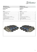
Summary of Contents for MPC2-S

Page 1: ...nbringen des Schutzblechs optional 13 Zusammenbau der Kontakte im Steckverbinder 16 Befestigung der feste Seite 20 Erdung von Metallteilen 21 Verbinden und Trennen des Steckverbinders 22 Notizen 24 Content Delivery status of components 2 Safety Instructions 3 4 Suggested tools 5 Cable preparation 8 Crimping 9 Coding 9 Marking 12 Fixing the protection plate optional 13 Assembling the contacts into ...

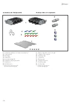
Page 2: ...ech 8 Halteklammern 1 Body configuration male or female 1 2 Contacts to be crimped 3 Retaining rings 4 Coding pins 5 Marking pins 6 Cable gland inserts 7 Protection plate 8 Locking clips 1 7 460xxxx ohne Kennzeichnungsstifte 7 461xxxx mit Kennzeichnungsstifte 1 7 460xxxx without marking pins 7 461xxxx with marking pins Lieferstatus der Komponenten Delivery status of components ...

Page 3: ...even de scribed as Stäubli compatible by certain manufacturers do not conform to the requirements for safe electrical connection with long term stability and for safety reasons must not be plugged together with Stäubli elements Stäubli therefore does not ac cept any liability for any damages resulting from mating such connectors i e lacking Stäubli approval with Stäubli elements Caution risk of el...

Page 4: ... the connector must be replaced Die Steckverbinder sind wasserdicht gemäß der für das jeweilige Produkt angegebenen IP Schutzart The plug connectors are watertight in accordance with the product specific IP protection class Nicht gesteckte Steckverbinder sind vor Feuchtigkeit und Schmutz zu schützen Die Steckverbinder dürfen nicht in ver schmutztem Zustand miteinander gesteckt werden Unmated plug ...

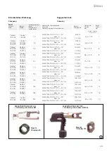
Page 5: ...9 2307 19 2315 50 MECATRACTION SU 210 K S21 oder or MECATRACTION EU 1370 U137C12 TN50V20 C12TN50 11 0 15 12 Contact 19 2216 19 2222 Contact 19 2316 19 2322 70 MECATRACTION SU 210 K S21 oder or MECATRACTION EU 1370 U137C12 TN70V20 C12TN70 12 6 0 15 12 Contact 19 2217 19 2223 Contact 19 2317 19 2323 95 MECATRACTION SU 210 K S21 oder or MECATRACTION EU 1370 U137C12 TN95V20 C12TN95 14 6 0 15 13 Contac...

Page 6: ... 2620 19 2622 and 19 2624 on sockets 19 2302 to 19 2334 ill 4 Lange gerade Verlängerung für Öff nungszange für Haltering 19 2933 Typ MPC TO LES PL Bestell Nr 19 2935 2 Stück bestellen Zur Demontage der Halteringe von den Steckern 19 2202 bis 19 2233 ill 4 Long extensions straight for opening pliers 19 2933 Type MPC TO LES PL Order No 19 2935 to order by 2 pieces To be used to dismount the retainin...

Page 7: ...ews flat side on 6 mm Length 140 mm Type MPC TO SCD M8 Order No 19 2940 ill 9 Flachrundzange Der Zangenkopf sollte so dimensioniert sein dass er in die oben dargestellte Öffnung passt Zum Beispiel FACOM nicht im Lieferprogramm von Stäubli Bestell Nr 193 16 CPE ill 9 Short half round nose pliers Use a pliers corresponding to the above dimensions For example FACOM not provided by Stäubli ref 193 16 ...

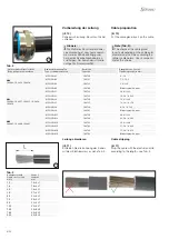
Page 8: ...chnitt Cable cross section mm2 Länge L Length L mm 10 14 4 1 16 16 4 1 25 18 4 1 35 21 4 1 50 23 4 1 70 28 4 1 95 33 4 1 120 33 4 1 150 35 5 2 185 40 5 2 240 40 5 2 Steckverbinderkörper Isolation Body configuration insulation Kabelverschraubung Typ Type of cable gland insert Bestell Nr Order No Anzugsbereich in mm Tightening range in mm M20 19 2862 19 2854 19 2856 MPC CG K1 19 2730 9 14 MPC CG K2 ...

Page 9: ...han insert a pin according to the following coding table The final position of the coding pin is obtained when it comes to a stop in the insulation a click can be heard Crimpen Crimping ill 12 Abisolierte Kabel bis zum Anschlag in Crimp Kontakt einführen Crimpen Sie die Hülse mit dem korrekten Einsatz Tab 1 Der Leiter muss im Sichtloch sichtbar sein Bitte achten Sie darauf dass die beiden Crimp Ei...

Page 10: ...u lorsqu il arrive en butée dans l isolant lorsqu un clic sonore est obtenu An example of a coding scheme is proposed by choosing the two lines of code contats the 2 ends whatever the number of poles Thus looking at the connection faces the letter A of the fixed part will be contrasted with the letter A of the mobile part Un exemple de système de codage est proposé en choisissant de coder les deux...

Page 11: ...Varianten Single pole versions coding feste Seite Fixe side Position Typ Type Bestell Nr Order No Bezeichnung Description 1 MPC CP SS BX 19 2631 Kodierstift Coding pin MPC S Gegenstück MPC S MPC S versus MPC S mobile Seite Mobile side ...

Page 12: ...4 5 Note Configuration codification 7460xxxx without marking pins 7461xxxx with marking pins 1 2 3 4 Beispiel 3 poliger Steckverbinder körper 7461xxxx mit Kodierung 1 2 und 3 Example of 3 poles configuration 7461xxxx with 1 2 and 3 marking Kennzeichnung Number or letter Farbe Color Bestell Nr Pin order No leer blank rot red 19 2660 22 leer blank blau blue 19 2660 23 leer blank gelb yellow 19 2660 ...

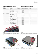
Page 13: ...e cable gland direction Applikation Application Steckverbinderkörper Isola tionsgröße Body configuration insulation size Polanzahl Pole number Bestell Nr Schutzblech aus Metall Metallic protection plate order no Anzahl Klammern 19 2550 pro Platte Number of clips 19 2550 by plate MPC S auf on MPC S Größe 1 Size 1 45 mm x 45 mm für Kontakte for contacts Ø 8 Ø 14 mm 1 19 2516 2 2 19 2517 4 3 19 2518 ...

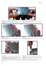
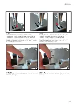
Page 14: ...tioned at the end in the side plates grooves ill 21 22 Achten Sie darauf dass die vorgestanzten Arretierungen A und B richtig positioniert sind Drücken Sie die Arretierungen mit der Flachrundzange herunter um sie einzurasten Drücken Sie von der Seite der Kabelverschraubung her gegen die Platte um zu prüfen ob sie sicher von den Arretierungen A und B gehalten wird ill 21 22 Make sure that the pre c...

Page 15: ...ungen des Schutzblechs ill 23 With the short half round nose pliers place the locking clips in the M marked positions for a male connector in the F marked positions for a female connector Repeat this operation as many times as they are M or F marked holes in the protection plate ill 24 25 Prüfen Sie die Klammern auf festen Sitz indem Sie versuchen sie von Hand zu bewegen ill 24 25 Make sure the cl...

Page 16: ...arrow Zusammenbau der Kontakte im Steckverbinder Assembling the contacts into the body of the con nector Befestigung der Buchsen Fixing sockets Wählen Sie anhand des Durchmessers des Crimpkontakts die Teilenummer für den Haltering aus Tab 6 aus Choose the retaining ring order no depending on the crimping contact diameter according to Tab 6 ill 28 Führen Sie das Kabel mit dem Crimpkontakt bis zum E...

Page 17: ...0 Insert the retaining ring in the groove of the contact with the opening pliers 19 2933 Check that the retaining ring is correctly placed Befestigung der Stecker Fixing the plugs Wählen Sie anhand des Durchmessers des Crimpkontakts die Teilenummer für den Haltering aus Tab 7 aus Choose the part number of the retaining ring depending on the crimping contact diameter in Tab 7 ill 31 Führen Sie das ...

Page 18: ...in ill 34 Insert the retaining ring mounting tool from the front side ill 35 Schrauben Sie das Werkzeug auf den Stecker ill 35 Screw the retaining ring mounting tool on the plug ill 36 Schrauben Sie das Werkzeug bis zum Anschlag des Isolators fest ill 36 The mounting tool comes to a stop when it touches the insulator ill 37 Drücken Sie den Knopf an der Rück seite des Werkzeugs bis zum Anschlag bis...

Page 19: ...ing the torque wrench and inserts ill 6 depending on the cable gland The recommended torques are Cable gland CG K M20 10 Nm Cable gland CG L M32 15 Nm Cable gland CG M M40 20 Nm Repeat this operation as many times as pole number Hinweis Die Kabelverschraubungen sind nicht für dynamische Anwendungen Seitwärtsbewegungen geeignet Für diese Anwendungen muss die Dy namic Cable Option DCO verwendet werd...

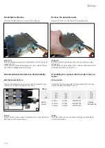
Page 20: ...x 60 mm minimal Größe 2 Sechskantschraube M8 x 70 mm minimal Empfohlenes Drehmoment 12 bis 13 Nm Tighten the 4 screws of the fixed part with screwdriver Allen for M8 screw ill 8 Size 1 hex screw M8 x 60 mm mini Size 2 hex screw M8 x 70 mm mini Tightening torque 12 13 Nm Größe Isolation Insulator size Anzahl Isolation Insulator quantity X mm Y mm D mm Größe 1 Size 1 Kontakt Contact Ø 8 mm Ø 14 mm 1...

Page 21: ...allenen Endplatte ist eine Edelstahlmutter A2 70 angebracht die Mutter ist an der Rückseite auf die Endplatte gecrimpt ill 48 In order to connect a grounding cable respect the dimensions in Tab 9 and take care to not go over the depth max of the fixation hole see max lenght in the table Don t damage the insulator The metallic end plate is equipped with an Stainless stell A2 70 nut the nut is crimp...

Page 22: ...die 2 Inbusschrauben M8 in den Endplatten mit einem Inbusschlüssel fest Empfohlenes Drehmoment zwischen 12 und 13 Nm ill 50 51 Screw the 2 hex screws M8 located in the end plates using an Allen screwdriver Recommended torque between 12 and 13 Nm ill 52 Stellen Sie sicher dass die Metallteile korrekt verbunden sind Es darf kein Spalt zwischen den Seitenteilen vorhanden sein ill 52 Make sure that me...

Page 23: ...n M8 mit einem Inbussschraubendreher ill 8 aus den Endplatten lösen und den mobilen Teil des Steck verbinders abziehen Unscrew the 2 M8 hex screws located in the end plates by using the screwdriver ill 8 then disconnect the mobile part of your connector ...

Page 24: ...n 8 4123 Allschwil Switzerland Tel 41 61 306 55 55 Fax 41 61 306 55 56 mail ec ch staubli com www staubli com electrical by Stäubli Electrical Connectors AG Switzerland MA403 12 2019 Index c Marketing Communications Änderungen vorbehalten Subject to alterations Notizen Notes ...

Reviews: