Mobile filter system
12 / 32
3 Machine description
3 Machine description
3.1 Overview
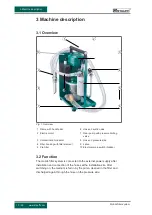
Fig. 1: Overview
1
Frame with handle bar
6
Hose on suction side
2
Electric motor
7
Gear pump with pressure limiting
valve
3
Contamination indicator
8
Hose on pressure side
4
Filter housing with filter element
9
Lance
5
Pre-filter
10
Electrical main switch (hidden)
3.2 Function
The mobile filter system is connected to the external power supply after
installation and connection of the hoses at the installation site. After
switching on, the medium is fed in by the pump, cleaned in the filter and
discharged again through the hose on the pressure side.
6
7
5
8
4
9
3
10
2
1


