background image


www.stavior.com


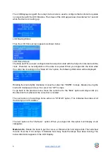
The LCD Display along with the rotary knob encoder is used to configure the Controller to operate 
in conjunction with the UVC Modules. The screen of the LCD appears as shown below for 1 second 
while the device is booting up. 


LCD Booting Status 
 
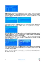
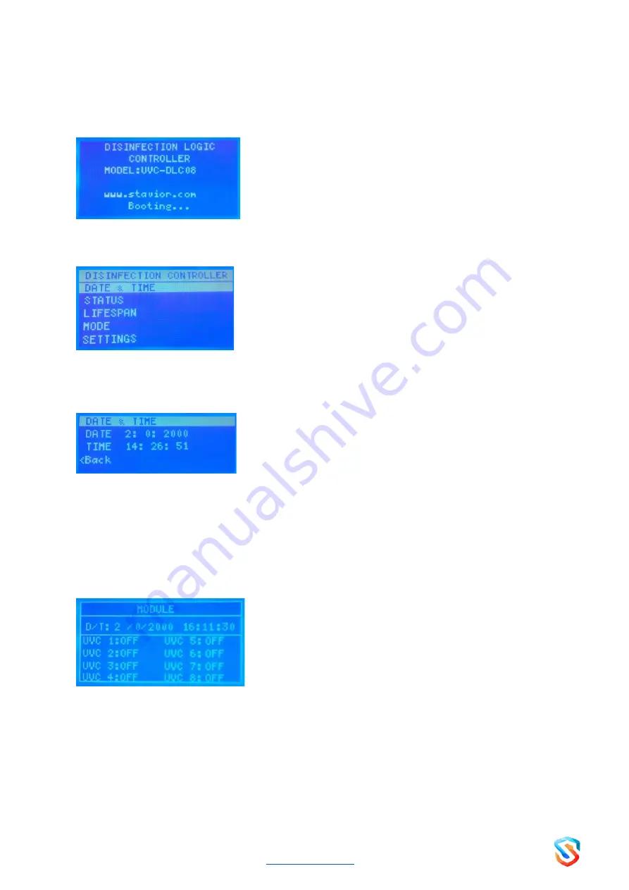
Then the LCD Home screen appears as shown below 


LCD Home Screen 
The Date and Time are pre-configured and are kept accurate with the help of an internal real-time 
clock. Therefore no reconfiguration of the date is required. When you single click the knob while 
the cursor bar is resting on the “Date & Time” option, the following information will be displayed. 


Rotating the knob slightly clockwise, moves the cursor bar “DOWN” in steps, likewise moving the 
knob anti clockwise will move the cursor bar “UP” in steps.  
To go back to the previous menu, move the cursor bar to the “Back” option and single click (or) 
Double click from wherever the cursor bar is located.  
 
The next option in the settings hom

e screen is “STATUS” option. This indicates the status of all 

the 8 lamps, on/off condition. 


The next option is the “Life Span”  option. When you single click this option it will display 2 sub 
categories.  
 

Module Life :


Rotate the knob to get the cursor on “Module Life” and single click. That will show 

the Life of all the 8  UV Lamps. It indicates how many hours the lamps have been burning. The 
below information appears in the LCD Display. 

Summary of Contents for Smart Sterilizer Series

Page 1: ...DISINFECTION LOGIC CONTROLLER UVC DLC08 User Manual English...

Page 2: ...ly and pay attention to all the warnings before using the Sterilizer PROPER AND SAFE USE OF THE DLC CONTROLLER The appliance is designed with built in safety features but it s important to follow all...

Page 3: ...r replace DLC Controller according to the instructions provided in the Installation section 3 Only qualified technicians or engineer should install or operate the DLC Controller 4 Do not operate the u...

Page 4: ...and scheduling operations lamp as per desired times and durations The UV Lamps are connected through the 8 Pin output Phase 8 Pin Output Neutral and the lamp switching operations and on off duration a...

Page 5: ...information will be displayed Rotating the knob slightly clockwise moves the cursor bar DOWN in steps likewise moving the knob anti clockwise will move the cursor bar UP in steps To go back to the pre...

Page 6: ...o be switched on off controlled manually with no reference to real time clock If the Auto mode is ON then the lamps are automatically switched on off based on the time configured already To change the...

Page 7: ...he Wifi Settings option Single click to edit the setting as Enable or Disable SPECIFICATIONS Dimensions 200 x 255 x 95 Cm Materials PVC 100 Shock Proof Power Source 230 V Frequency 50 60 Hz Power Cons...

Page 8: ...er input failure to the device Check the power supply from the nearby power source is on off MCB Tripped Try resetting the MCB Lamps won t glow UVC Switch is off MCB is switched off Turn ON UVC Switch...

Page 9: ...roller is faulty A There are no user serviceable parts inside this unit Please contact the manufacturer or distributor as soon as possible HEAD OFFICE REGD OFFICE Cenaura Technologies Pvt Ltd Cenaura...

Reviews: