background image


www.stavior.com


sensitive. 

Original Equipment Manufacturer. 


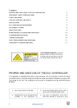
Only  a  well  qualified  technician  or 

engineer  should  be  using  or 
operating  this  controller  after 

properly  understanding  the  safety 
aspects and  operational concepts of 

the DLC Controller 


Protect  yourself  all  the  times  from  any 

kind of Electric Shock. 


IMPORTANT SAFETY PRECAUTIONS 

To reduce the risk of fire, electric shock, injury, follow the precautions diligently: 
1.  Read all instructions in the User Manual carefully before using the appliance. 
2.  Install  or  replace  DLC  Controller  according  to  the  instructions  provided  in  th

e  “Installation” 

section. 

3.  Only qualified technicians or engineer should install or operate the DLC Controller 
4.  Do not operate the unit if the electric cord or plug, cables, buttons, etc are loose or damaged. 
5.  Mount the Unit as per the Installation Instruction of the manual. 
6.  Ensure this Unit is Installed in a neat, clean, dry environment without dust. 
7.  Do not store or use this appliance outdoors. 
8.  Keep the unit away from moisture or wet environment. 
9.  Place the unit at locations away from heated surfaces. 
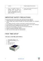
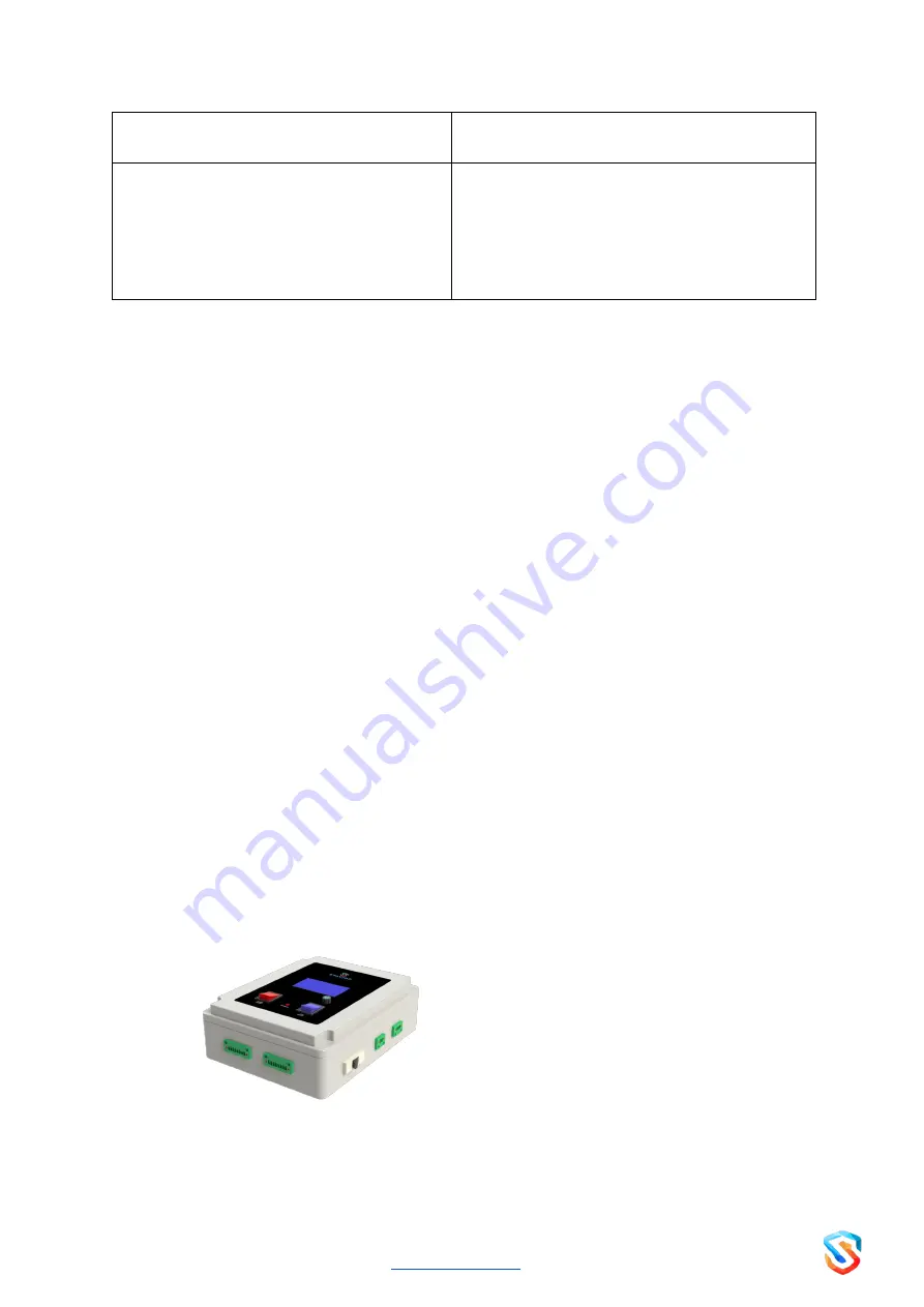
 

FIRST TIME SETUP 

THE DLC CONTROLLER PARTS 


1.  Lamps Phase Output (1 - 8) 
2.  Lamps Neutral (Output) (1 - 8) 
3.  MCB           
4.  Door Switch Sensor 
5.  Input 230 V AC 


Summary of Contents for Smart Sterilizer Series

Page 1: ...DISINFECTION LOGIC CONTROLLER UVC DLC08 User Manual English...

Page 2: ...ly and pay attention to all the warnings before using the Sterilizer PROPER AND SAFE USE OF THE DLC CONTROLLER The appliance is designed with built in safety features but it s important to follow all...

Page 3: ...r replace DLC Controller according to the instructions provided in the Installation section 3 Only qualified technicians or engineer should install or operate the DLC Controller 4 Do not operate the u...

Page 4: ...and scheduling operations lamp as per desired times and durations The UV Lamps are connected through the 8 Pin output Phase 8 Pin Output Neutral and the lamp switching operations and on off duration a...

Page 5: ...information will be displayed Rotating the knob slightly clockwise moves the cursor bar DOWN in steps likewise moving the knob anti clockwise will move the cursor bar UP in steps To go back to the pre...

Page 6: ...o be switched on off controlled manually with no reference to real time clock If the Auto mode is ON then the lamps are automatically switched on off based on the time configured already To change the...

Page 7: ...he Wifi Settings option Single click to edit the setting as Enable or Disable SPECIFICATIONS Dimensions 200 x 255 x 95 Cm Materials PVC 100 Shock Proof Power Source 230 V Frequency 50 60 Hz Power Cons...

Page 8: ...er input failure to the device Check the power supply from the nearby power source is on off MCB Tripped Try resetting the MCB Lamps won t glow UVC Switch is off MCB is switched off Turn ON UVC Switch...

Page 9: ...roller is faulty A There are no user serviceable parts inside this unit Please contact the manufacturer or distributor as soon as possible HEAD OFFICE REGD OFFICE Cenaura Technologies Pvt Ltd Cenaura...

Reviews: