

4
INSTALLATION STEPS
1. Please note the installation has to be performed by a trained technician
2. Remove all packing material and accessories.
3. Install the DLC Controller at a height of at least 1.5 meters above the ground.
4. Use Steel Bolts if mounting on concrete surfaces.
5. Ensure the wiring connection is properly secured, connected with correct polarity.
6.
The controller shall be installed in an area that’s easily accessible.
7. The Controller should be installed away from heat generating sources, wet environment,
dusty environment, or other High Voltage Sources.
8. Use input voltage
230 V and Frequency: 50/60Hz.
9. Connecting wires
– Yellow (Phase), Black (neutral), Green (Earthing)
PRECAUTIONS TO BE TAKEN
Avoid the following situations:
●
Avoid mounting the DLC Controller near heat sources, such as heating vents, air
conditioning units, High Voltage Sources etc.
DLC CONTROLLER OPERATION
HOW DOES IT WORK
The Disinfection Logic Controller Unit controls the UVC Module switching and scheduling
operations lamp as per desired times and durations. The UV Lamps are connected through the 8
Pin output (Phase) & 8 Pin Output (Neutral) and the lamp switching operations and on/off duration
are controlled by the internal programming and relay circuit.
The Unit operates on 230 V AC Input connected through a 3 Pin Socket. The Main Power Switch
on the Front Door is used to switch on/off the power supply to the Controller. The UV Power switch
adds an additional layer of security to control the switching of UVC lamps. An Indicator light is
provided adjacent to the Main Power switch along with an Alarm to indicate/warn personnel safety.
A green light means it is safe for the people to enter the AHU or control room. As soon as the UV
Power Switches ON, the indicator turns RED and the UV Lamps switch ON, indicating a hazard
for any personnel entering the UV Lamps area. A 2 pin door switch is also provided that activates
alarm when the door is open while the UV Lamps are ON.
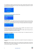
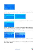
The LCD Display on the panel helps understand the status of the UV Lamps. The programming
features can be set / configured with the help of the knob adjacent to the LCD display.
DLC Settings Configuration


