gb
/
18
/
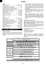
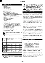
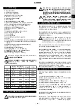
1. PART LIST Fig.1
1. Filter holder.
2. Protective inner lens.
3. Fixed / automatic filter.
4. Control of degree of protection.
5. Frame fastening screw.
6. Protective outer lens.
7. Textile band of sweat.
8. Harness height adjustment band.
9. Angle adjustment plate in working position.
10.Attemming adjustment of the harness perimeter band.
11. Retaining bolt for adjustment plate # 9.
12. Screws for attaching the harness to the helmet.
13.Mounting the locking nut of the harness to the hull.
14.Casco.
15. Setting the sensitivity to dark.
16. Set standby to clear.
17. Right clip.
18. Left clip.
19. Shade regulating potentiometer
20.Casco
21. Right clip (AS-X/AS-XP/AS-R/AS-RT/CARNIVAL)
22. Left Clip (AS-X/AS-XP/AS-R/AS-RT/CARNIVAL)
23. Reset button (self-diagnostics-safety ADF (AS-XL)
24. Filter attachment holes (AS-XL)
25. Filter attachment bar (AS-XL)
26. Filter retention straps (AS-XL)
27. Replaceable Battery Housing (AS-XL)
28. Battery Indicator (AS-XL)
29. Complete Clips Set (AS-XL)
Protect this manual and have it available to the
user.
Read and understand completely this manual
before using this product.
External
Protector
Protector
Interno
Harness
Filter
FIG
6.
2.
8.
3.
AS-XP
4020.48
4020.47
4020.19
4020.31
AS-X
4020.8
4020.13
4020.19
4020.18
AS-XL
4020.29
4020.30
4020.42
4020.27
AS-R/
AS-R
4020.8
4020.57
4020.55
4020.53
AS-RT/
CARNIVAL
4020.8
4020.59
4020.55
4020.61
AS-1D
4020.58
4020.59
4020.60
4020.61
GS-0
-
8110.1220
8110.1221
8110.1219
2. SPARES
Do not use any solder equipment without prior
training.
Do not use equipment if you are not prepared
for its use. Before each use, inspect the
equipment as explained in this manual to
insure that equipment is in perfect state.
Do not make any modifications to equipment
other than mentioned in this manual. Do not
use replacement part other than mentioned in
this manual.
3. USE LIMITATIONS
Do not work under possible sever impact conditions. This
equipment is designed to protect under normal welding conditions.
Do not work out of the margins of this equipments design.
This equipment does not protect against corrosive liquids
or in an explosive atmosphere.
Do not work out of the margins of this equipments design.
Using this equipment with temperatures lower than -5ºC
or higher than 55ºC effects filter design and could cause
permanent damage to the eyes and even loss of vision.
This equipment must be used for overhead welding and
laser cutting and welding.
This equipment is not designed to work in wet conditions
or in water. Do not submerge in liquid.
Do not work out of the margins of this equipments design.
The use of this equipment in any other type of activity that
requires a level of protection higher than 13 could cause
permanent damage to the eyes and even a loss of vision.
This equipment is not designed to be used with laser cutting
or any other work that requires a grade greater than 13.
Do not use this equipment in extensive overhead soldering.
Dangerous burns could be received if there is a possibility
of droppings from molten metal. Do not use dissolvent on
the filter or helmet.
4. CHARACTERISTICS
The mask “stayer welding” are composed by four main
parts:
1.
Helmet sell STAYER EN 175 F
(Fig nº 14).
2.
Automatic darkening filter 4/9-13 STAYER
1/3/2/2/379
(Fig nº 3).
3.
Front cover lens STAYER 1 F
(Fig nº 6).
4.
Back cover lens STAYER 1 S
(Fig nº 2)
Explanation of helmet sell STAYER EN 175 F
STAYER=manufacturer code, EN 175= number of testing
standard, F=symbol for low energy impact (45m/s).
Explanation of automatic darkening filter 4/9-13 STAYER
1/3/2/2/379.
Explanation: 4 = light state, 9-13 = dark states, STAYER
= manufacturer code, 1 = optical class, 3 = diffusion of
light class, 2 = homogeneity class, 2 = angle dependence
class, 379 = number of testing standard.


