/
21
/
es
it
gb
fr
p
pl
cz
el
The AS-XL model has a range selector with three positions:
1. Shade range DIN 5-9.
2. Shade range DIN 9-13.
3. Grinding without shadow.
Select according to welding type. Generally, work in the
range 9-13 except for low intensity work such as low
intensity TIG or soft flame welding.
Grinding mode: in this mode the filter does not darken
avoid losing vision when used as a protector against
sparks projections.
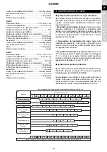
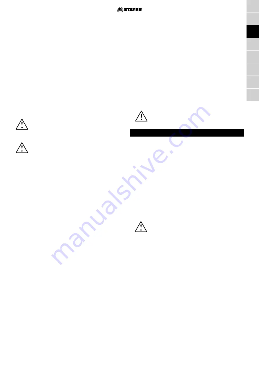
In the AS-XL model: Set knob 4 according to the following
table based on UNE EN 379: 2009-07.
These tables are valid for average working conditions,
where the distance from the observer’s eye to the molten
metal bath is approximately 50 cm and the average
illumination is about 100 lx.
The use of a degree of protection higher does
not necessarily proportion more protection
and obligates the user to close in on the
radiant source and breath harmful fumes.
It’s possible to use filters with one more
degree of protection when working in open
air where there is a strong natural illumination.
Adjusting sensibility (AS-1D/AS-X/AS-XP/AS-XL)
This regulation, labeled “SENSIVITY” (nº 15) calibrates
the minimum light intensity needed for darkening the filter.
Adjustment is continuous form minimum to maximum
but three standard position (min, medium and max) are
explained.
1. Min. (LO) Used when is used close to another welders
arcs. The purpose is to avoid not desired darkening
of the filter when other welders have established their
welding arc. Complementary to this use case is the
situation of high amperage welding.
2. Medium. This is the standard and initially recommended
position for medium amperages and / or sunlight
conditions.
3. Max. (HI) For use in covered and alone welding with
no interference with another welder’s arcs.
Complementary is the situation of low amperage
welding in no sunlight presence. Staring to sunlight
can fire darkening when filter is at maximum sensibility.
It is recommended to start adjustment at mid position
adjusting until the adequate adjustment is obtained.
Adjusting wait time (AS-1D/AS-X/AS-XP/AS-XL)
This regulation is named “DELAY” (nº 16) and sets the time
elapsed between the end of welding arc and the return to
clear state of the welding filter. Two limit use cases are
described, Min and Max positions.
1. Max. For using at high amperage welding with very
bright welding pool. In this case is desirable a slight
cool of pool before enable eye to see.
2. Min. In low amperage, quick cooled, situations were
immediate control is desired.
Initial position recommended is central one.
It is recommended to start adjustment at mid position
adjusting until the adequate adjustment is obtained.
Setting grinding
You can adjust your mask (AS-X/AS-R/AS-RT/AS-1D/
CARNIVAL/AS-R/AS-XP/AS-XL) as work either welding
or grinding.
1. To enable the mask grinding (AS-X/AS-R/AS-RT/AS-
1D/CARNIVAL/AS-XP/AS-XL) just put the controller in
position 17 GRIND.
To use the GS-0 mask in grinding operations, lift the fixed
filter until it stops.
Never leave the knob 17 in the grinding position.
Risk of glare if welded.
7. MAINTENANCE
Cleaning and Storage
Clean the equipment using a soft cloth, a medium soap
and lukewarm water. Do not use solvents.
Clean the automatic filter with a cloth that does no loose
fibers. Do not project sprays in equipment nor submerge.
Store equipment in a place that has a medium temperature
and is clean and dry without any dust.
Since the inner part of the outer filter can be get dirt with
the welding smoke is recommended to be dismantled and
cleaned regularly.
Replacing the protective lenses
The automatic filter 3 has two protective lens to protect
the other lens from smoke flying particles and arc spatter
during the welding process.
Use only original filters supplied by distributor.
Replacing the exterior protection (AS-X/AS-R/AS-R/
AS-RT/CARNIVAL/ AS-R / AS-XP)
To remove the protective filter:
1. Press downwards the flaps of the buttons
21-22
, on
both sides of the transparent screen.
2. Pull protector 6 while holding clips 21-22 to release
the clear shield.
Replacing the interior protection
1. Remove the interior protector
2
with index finger in the
groove supplied at upper side of filter.
2. Place the interior protector
2
by slightly bending in a
way so that it can be inserted into the four highlighted
corners.
3. Remove the protective film from the surface.
Replacing the harness
If the harness
8
is broken or does not adjust correctly,
proceed with its replacement.


