ENGLISH
5
5
-
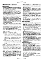
When working with the machine, always hold it
firmly with both hands and provide for a secure
stance.
The power tool is guided more secure with
both hands.
-
Secure the workpiece.
A workpiece clamped with
clamping devices or in a vice is held more secure than
by hand.
-
Always wait until the machine has come to a
complete stop before placing it down.
The tool insert
can jam and lead to loss of control over the power tool.
Product Description and Specifications
Read all safety warnings and all instructions.
Failure to follow the warnings and instructions may
result in electric shock, fire and/or serious injury.
While reading the operating instructions, unfold the
graphics page for the machine and leave it open.
Intended Use
The machine is intended for lengthways and crossways
cutting of wood with straight cutting lines as well as mitre
cuts in wood while resting firmly on the workpiece. With
suitable saw blades, thin-walled non-ferrous metals, e. g.,
profiles, can also be sawed.
Working ferrous metals is not permitted.
This manual is consistent with the date of manufacture of
your machine, you will find information on the technical
data of the machine acquired manual check for updates of
our machines on the website: www.grupostayer.com
Product Features
The numbering of the product features refers to the
illustration of the machine on the graphics page.
1 On/Off switch.
2 Lock-off button for On/Off switch.
3 Auxiliary handle (insulated gripping surface).
4 Spindle lock button.
5 Scale for mitre angle.
6 Wing bolt for bevel-angle preselection.
7 Wing bolt for parallel guide.
8 Cutting mark, 45°.
9 Cutting mark, 0°.
10 Parallel guide.
11 Retracting blade guard.
12 Base plate.
13 Lever for retracting blade guard.
14 Chip ejector.
15 Blade guard.
16 Handle (insulated gripping surface).
17 Key.
18 Clamping bolt with washer.
19 Clamping flange.
20 Saw blade*.
21 Mounting flange.
22 Saw spindle.
23 Extraction adapter*.
24 Clamping lever for cutting-depth preselection.
25 Cutting-depth scale.
*Accessories shown or described are not part of the standard
delivery scope of the product. A complete overview of accessories
can be found in our accessories program.
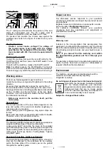
Technical data
= Voltage
= Battery power
= Load speed.
Ø
= Disc dimension.
=
Cutting capacity 90º
=
Cutting capacity 45º
=
Weight.
L
WA
= Sound power level.
L
PA
= Sound pressure level.
= Vibration.
Noise/Vibration Information
Sound emission values determined according to EN
60745-2-5. Typically the A-weighted noise levels of the
product are: Sound pressure level 96 dB(A); Sound power
level 107 dB(A). Uncertainty K =3 dB.
Wear hearing protection!
Vibration total values ah (triax vector sum) and uncertainty
K determined according to EN 60745-2-5:
ah<2.5m/s
2
, K=1.5m/s
2
.
The vibration level given in this information sheet has been
measured in accordance with a standardised test given in
EN 60745 and may be used to compare one tool with
another.
It may be used for a preliminary assessment of exposure.
The declared vibration emission level represents the
main applications of the tool. However if the tool is used
for different applications, with different accessories or
insertion tools or is poorly maintained, the vibration
emission may differ. This may significantly increase the
exposure level over the total working period.
An estimation of the level of exposure to vibration should
also take into account the times when the tool is switched
off or when it is running but not actually doing the job. This
may significantly reduce the exposure level over the total
working period.
Identify additional safety measures to protect the operator
from the effects of vibration such as: maintain the tool and
the accessories, keep the hands warm, organisation of
work patterns.
Declaration of conformity
The undersigned: STAYER IBERICA, S.A.
With address at:
Calle Sierra de Cazorla, 7
Área Empresarial Andalucía - Sector 1
28320 PINTO (MADRID)
Tel.:+34 91 691 86 30 / Fax: +34 91 691 86 31
Summary of Contents for CP L18
Page 2: ...2 2 ...


