ENGLISH
15
15
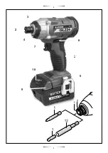
7 On/Off switch
8 Rotational direction switch
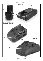
9 Battery unlocking button
10 Battery charge-control indicator
11 Charger
12 Universal bit holder
4. Operating instructions
Method of Operation
The tool holder 2 with the tool is driven by an electric
motor via a gear and impact mechanism.
The working procedure is divided into two phases:
Screwing in and tightening (impact mechanism in action).
The impact mechanism is activated as soon as the
screwed connection runs tight and thus load is put on the
motor. In this instance, the impact mechanism converts
the power of the motor to steady rotary impacts. loosening
screws or nuts, the process is reversed.
4.1 Placement and testing
Use only original lithium ion batteries with the voltage
listed on the nameplate of your power tool.
Using
otherbatteries can lead to injuries and pose a fire hazard.
Use of batteries not suitable for the machine can
lead to malfunctions of or cause damage to the
power tool.
Set the rotational direction switch
8
to the centre position
in order to avoid unintentional starting. Insert the charged
battery
5
into the handle so that it can be felt to engage
and faces flush against the handle.
Reversing the Rotational Direction
The rotational direction switch 8 is used to reverse the
rotational direction of the machine. However, this is not
possible with the On/Off switch 7 actuated.
Right rotation:
For driving in screws and tightening nuts,
press the rotational direction switch 8 through to the left stop.
Left Rotation:
For loosening and unscrewing screws and nuts,
press the rotational direction switch 8 through to the right stop.
Switching On and Off
To start the machine, press the On/Off switch
7
and keep it pres-
sed. The power light
4
lights up when the On/Off switch
7
is
slightly or completely pressed, and allows the work area to
be illuminated when lighting conditions are insufficient.
To switch
off
the machine, release the On/Off switch
7
.
Adjusting the Speed
The speed of the switched on power tool can be variably ad-
justed, depending on how far the On/Off switch
7
is pressed.
Light pressure on the On/Off switch 7 results in a low
rotational speed. Further pressure on the switch results in
an increase in speed.
4.2 Adjustment operation
Before any work on the machine itself (e. g.
maintenance, tool change, etc.) as well as during
transport and storage, remove the battery from
the power tool. There is danger of injury when
unintentionally actuating the On/Off switch.
Inserting
Pull the locking sleeve
3
forward, push the insert tool to
the stop into the tool holder
2
and release the locking
sleeve
3
to lock the insert tool. Use only screwdriver bits
with ball catch
1
. Other screwdriver bits can be used with
a universal bit holder with ball catch 12.
Removing
Pull the locking sleeve 3 forward and remove the insert tool.
Tips
Before screwing larger, longer screws into hard materials,
it is advisable to predrill a pilot hole with the core diameter
of the thread to approx. 2/3 of the screw length.
5. Maintenance and service instructions
Before any work on the machine itself, pull the mains
plug. For safe and proper working, always keep the
machine and ventilation slots clean.
Transport
The contained lithium-ion batteries are subject to the
Dangerous Goods Legislation requirements. The user can
transport the batteries by road without further requirements.
When being transported by third parties (e.g.: air transport
or forwarding agency), special requirements on packaging
and labelling must be observed. For preparation of the
item being shipped, consulting an expert for hazardous
material is required.
Dispatch batteries only when the housing is undamaged. Tape
or mask off open contacts and pack up the battery in such a
manner that it cannot move around in the packaging. Please
also observe possibly more detailed national regulations.
5.1 Cleaning
When the battery is no longer operative, please refer to an
authorised after-sales service agent for
STAYER
power tools. If
the machine should fail despite the care taken in manufacturing
and testing procedures, repair should be carried out by an
after-sales service centre for
STAYER
power tools.
5.2 Repair service
Our after-sales service responds to your questions concerning
maintenance and repair of your product as wellas spare
parts. Exploded views and information on spare parts can
also be found under:
info@grupostayer.com
Our customer
consultants answer your questions concerning best buy,
application and adjustment of products and accessories.
5.3 Warranty
Warranty card
Included in the documentation that
accompanies this equipment, you should find the warranty
card. You should fill out the card completely and return to
Summary of Contents for ISL122CK
Page 2: ...2 3 8 6 9 9 5 4 ISL122K ISL122CK 5 10 11...
Page 3: ...3 3 2 4 7 8 5 10 9 6 3...
Page 4: ...10 11 9 5 10 11 ISL122 K ISL222K ISL224K 10 10 IWL20...
Page 37: ...NOTAS 37...
Page 38: ...NOTAS 38...
Page 39: ...NOTAS 39...


