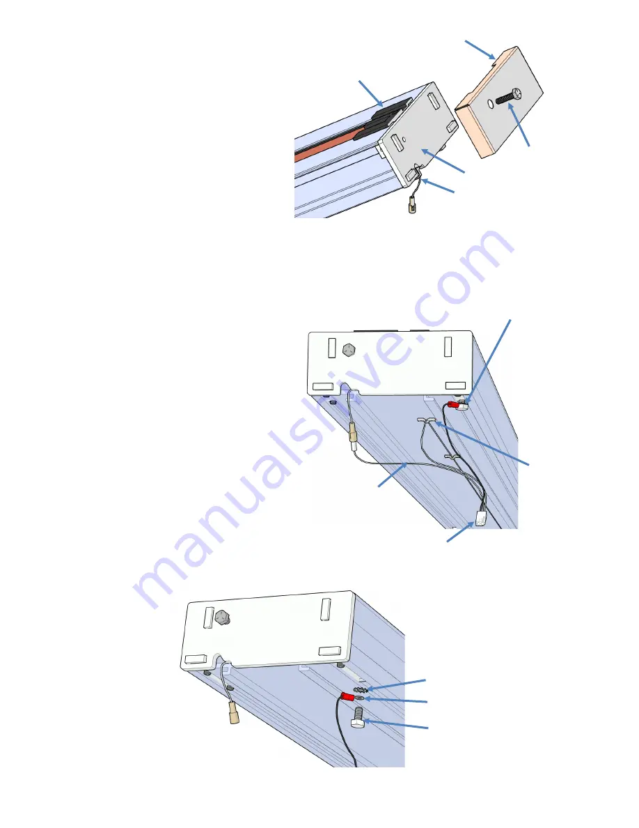
background image


11


Star Lock Washer


Retaining Ring


Hex Head Screw


Limit 

Cam


End Cap


End Plate


Gear Rack 


Compression 
Screw


Route the 
Charge Wire 
through the slot 
in the End Plate


Place the upper limit cam inside the track 
and secure by tightening the phillips head 
screw.


Place the end plate onto the end of the track 
while routing the charge wire through the 
slot in the bottom of the end plate.  Tighten 
the set screws in the end plate.


Place the end cap onto the end plate and 


secure with adhesive back tape.


Insert the gear rack compression screw and 
tighten to compress the gear rack pieces 


together.  The screw must make contact with 
the gear rack.  If the screw is too short, there 
is a longer one with the small parts.


The battery charger can be placed at the top or 
bottom of the track.  

The illustration shows the 

charger being at the top end of the track.


Connect the short white wire to the mating 
connector from the top charge strip.


Route the long white wire to the bottom of the 
track and connect it to the mating connector 
from the bottom charge strip.  

Adhesive back U

-

clips are provided to be applied to the bottom 

of the track for wire routing.


Remove the hex head screw and star lock 
washer from the bottom of the end plate and 
connect the black wire to the end plate.  Con-
nect the harness to the charger.


Hex head screw 
with Ring Terminal 
(Black Wire)


White Wires


U

-

Clip


To Charger


Plug the charger into 110V outlet.


Summary of Contents for SL19

Page 1: ...1 Model SL19 Installation Manual February 24 2021 Serial Tag Rev J Staying Home Corporation 2501 Anaconda Road Harrisonville MO 64701 816 380 2427 www stayinghome com...

Page 2: ...ic cams _____ Footrest _____ Seat _____ Battery Charger with 6 cord _____ Header cover _____ Upper and lower track end caps ____ 2 Wireless call send key fobs _____ Small parts bag _____ Installation...

Page 3: ...Folding Footrest Folding Seat Safety Pan Limit Cam Extruded Aluminum Track Manual Lowering Access Unit Control under Armrest Circuit Breaker Reset Switch Install Switch LED Diagnostic Indicator Access...

Page 4: ...4 Underside of Chassis Upper Limit Switch Final Limit Switch Overspeed Governor Pinion Gear Drive Pinion Gear Lower Limit Switch Charging Contact...

Page 5: ...t on the end of the gear racks indicates that end has been precision machined Only butt up the ends of gear racks that are red If the end is not painted it must be put toward the end of the track Uppe...

Page 6: ...e if the track is to be installed on the left side or right side The gear rack should always be located on the right side of the track regardless of which side of the stairs the track is mounted Measu...

Page 7: ...Gear rack is always on the right side as you look up from the bottom Apply a light coat of lithium grease on the gear rack and vertical sides of the track Left Hand Installation Right Hand Installatio...

Page 8: ...ap the large end of the 3 16 pin half way into one of the tracks Slide the other track onto the splice ensuring that the track pieces align on all sides Tighten the remaining set screws to lock everyt...

Page 9: ...the top of the rail The rail brackets are designed to lean the track toward the wall to offset the weight of the unit and user therefore the nuts on brackets should be on the staircase side toward the...

Page 10: ...into the top end of the track Flip the red RESET OFF switch to the RESET position The lift will beep and the LED indicator will turn red yellow green The chassis is now ready to be run down onto the g...

Page 11: ...ake contact with the gear rack If the screw is too short there is a longer one with the small parts The battery charger can be placed at the top or bottom of the track The illustration shows the charg...

Page 12: ...crews on the chassis Use the keyhole pattern that offsets the footrest assembly toward the top end of the chassis Connect the wire harnesses between the chassis and footrest assembly Level the footres...

Page 13: ...seat control through the hole in the back of the footrest verti cal plate and connect to the mating connector Replace the front cover on the footrest assembly Turn on the red RESET OFF switch to powe...

Page 14: ...g code If a key fob needs to be programmed 1 Press the program button on the RF receiver 5 times until the letter A is displayed There should now be a slow flashing dot on the display 2 Press and hold...

Page 15: ...age under 22 5 volts 2 YELLOW FLASHES 1 2 Second beep Seat Swivel Latch Sensor 3 YELLOW FLASHES 1 2 Second beep Footrest Obstruction Sensor 2 RED FLASHES 3 Second beep Sensor Fault 2 or more sensors e...

Page 16: ...ther all purpose grease tube of lubricant is provided _______ Verify the top track cover is securely fastened to the track _______ Verify the inside of the track is free of foreign objects Footrest __...

Reviews: