background image

12

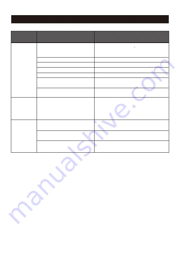
POSSIBLE CAUSE

PROBLEM

SOLUTIONS

The pressure is

low or there is

not enough air. 

There is

moisture in the

discharge air.

The compressor

overheats.

TROUBLESHOOTING

There is a leak at one of the fittings.

The tank drain valve is open.
The air intake is restricted.
Prolonged excessive use of air.
There is a hole in the air hose.
The tank leaks.

The valve is leaking.

There is condensation in the air tank 

caused by a high level of atmospheric 

humidity or because the air 

compressor has not been running long 

enough.
The ventilation is inadequate.

Cooling surfaces are dirty.

The valve is leaking. 

Check the fittings with soapy water. Tighten or 

reseal leaking fittings (apply plumber s tape on 

threads).Do not over tighten.
Close the drain valve.
Clean or replace the air filter element.
Decrease the amount of air used.
Check the air hose and replace it if necessary.
Replace the tank immediately. Do not attempt to 

repair it.
Check for worn parts and replace them if 

necessary.
Drain the air tank after each use. Drain the air 

tank more often in humid weather and use an 

air-line filter.

Relocate the compressor to an area with cool, dry 

and well-circulated air.

Clean all cooling surfaces on the pump and the 

motor thoroughly.

Replace worn parts and reassemble using new 

plumber's tape.

Summary of Contents for 3331282

Page 1: ...ressor To Reduce The Risk Of Injury User Must Read And Understand Operator s Manual Save These Instructions For Future Reference Toll Free Helpline OPERATOR S MANUAL CAUTION 1 888 899 0146 Product Mod...

Page 2: ...s Read all instructions and follow them with use of this product CFM Cubic Feet per Minute This compressor is rated in accordance with ISO 1217 displacement compressors acceptance tests TECHNICAL SPEC...

Page 3: ...sure that the procedure work method or operating technique that you choose does not render the compressor unsafe The safety alert symbol indicates a potential hazard to personal injury A signal word D...

Page 4: ...erious injury Risk of serious eye injury Always wear ANSI Z87 1 approved safety goggles when using air compressor Do not spray any part of the body Shock risk could result in death or serious injury O...

Page 5: ...r Pressure Regulator G Outlet Pressure Gauge F Tank Pressure Gauge D ON OFF Switch H Quick Coupler B Air Compressor Pump A Electrical Motor J Air Tank I Drain Valve C Safety Valve D J I H F E G A B K...

Page 6: ...wise to decrease the pressure Tank Pressure Gauge The gauge measures the pressure level of the air that is stored in the tank It cannot be adjusted by the operator and it does not indicate the pressur...

Page 7: ...air hose 1 to the compressor s quick coupler 2 with the quick conncetor 3 Fig B Air hose and quick connector are not provided need to be purchased sepa rately Apply plumber s tape on all the threads...

Page 8: ...ng in the unit is noly requiresd prior to first use Fig F After 30 minutes turn off the ON OFF switch Close the tank drain valve 1 by turning it clockwise Fig G Set the ON OFF switch to the ON positio...

Page 9: ...d pressure is reached The compressor is ready for use Set the ON OFF switch 1 to the OFF position Unplug the power cord 2 Reduce the pressure in the tank through the outlet hose Pulling the safety val...

Page 10: ...ect and wind up the power cord Clean the ventilation openings on the motor enclosure with a damp cloth Drain all moisture from the tank Pull the pressure safety valve to release all pressure from the...

Page 11: ...gauge and cord length Turn the air compressor off unplug the power cord and wait until the motor has cooled down Plug in the power cord only after the motor has cooled down and wait at least 5 minutes...

Page 12: ...equate Cooling surfaces are dirty The valve is leaking Check the fittings with soapy water Tighten or reseal leaking fittings apply plumber s tape on threads Do not over tighten Close the drain valve...

Page 13: ...13 EXPLODED VIEW...

Page 14: ...d Screw M4x12 Screw M4x10 Capacitor Shroud Capacitor Bolt M5x12 Elbow Fitting 1 1 1 1 1 2 1 3 1 2 1 2 2 1 1 1 6 2 4 2 Pump Cover 1 Description Qty No 22 23 24 25 26 27 28 29 30 31 32 33 34 35 36 37 38...

Page 15: ...dress below and call 1 888 899 0146 for instructions prior returning this item to the store or sending back to We will inspect the product and contact you within 72 hours to give you the results of ou...

Reviews: