background image

INSTALLATION, OPERATION & MAINTENANCE MANUAL

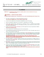
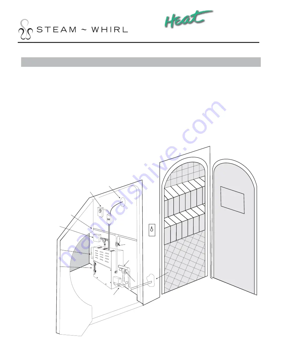
 1.  Place the steam generator, optional Thermostat Controller (TC-2) and optional 24 Hr 7 Day Timer in a location 

NOT ACCESSIBLE TO CLIENTS

 but that is 

ACCESSIBLE TO MAINTENANCE

 and not more than 40’ from 

steam room.  

ALL 

steam generators require maintenance.

 2.  The steam generator should never be located where it is exposed to outside weather conditions or freezing 

temperatures, near fl ammable materials, inside the steam room or where access cannot be gained to Water Level 
Sensor Probe for maintenance.

 3.  Install in an upright and level position.

 4.  The serial number label should be visible and accessible for service.

 5.  A minimum of 2’ of open unobstructed space must be left around the top and sides of the generator to allow for 

heat dissipation and accessibility for service.

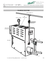
INSTALLATION

Steam

Room

24 H Timer

for

Blowdown

24 Hr/7 Day Timer

for TC-2

Water

Supply

Line

A

C

D

E

F

B

Site Glass

Temperature

Sensor Probe

Optional

60 Min 

Timer

STEAM-WHIRL

A

Power Box

&

Power Disconnect

TC-2

G

Spa Kur Therapy

Development

Inc

H-e-a-t Spa Kur Therapy Development Inc — Tel 707-942-6633 — Fax 707-942-0734 — www.h-e-a-t.com

6/20

Summary of Contents for SW-10-3BD

Page 1: ...Health Relaxation Exhilaration Commercial Series Installation Instructions Heat Spa Kur Therapy Development Inc...

Page 2: ...al door is not necessary 9 Make sure there is a floor drain for condensation run off and cleaning 10 Do not install a fan inside steam room Hot steam rises and will escape through flapper 11 Windows t...

Page 3: ...anty Factory assistance provided from blueprint to finished product Multiply the length x width x height of the steam room enclosure A A Cubic Feet If enclosure walls are constructed of glass marble c...

Page 4: ...BD 800 18 240 1 75 100A 3AWG SW 18 3BD 3 43 60A 6AWG SW 18 8BD 208 1 87 110A 2AWG SW 18 83BD 3 50 70A 6AWG BD Blowdown Factory Installed Commercial Series models contain 1 Steam Generator w Pressure G...

Page 5: ...ody temperature of 98 6 F The symptoms of hyperthermia include an increase in the internal temperature of the body dizziness lethargy drowsiness and fainting 2 The effects of hyperthermia include Fail...

Page 6: ...annot be gained to Water Level Sensor Probe for maintenance 3 Install in an upright and level position 4 The serial number label should be visible and accessible for service 5 A minimum of 2 of open u...

Page 7: ...nished floor in shower or just above deck of bathtub on any wall not interfering with user and at least 12 14 away from seat or bench For areas with acrylic or other non heat resistant floors install...

Page 8: ...ass E C F A STEAM WHIRL STEAM BATH GENERATOR MODEL NO SER NO VOLTS PH AMPS KW MFG BY STEAM WHIRL PRODUCTS LAS VEGAS NV 89118 702 270 2124 LISTED 16K3 STEAMBATH EQUIPMENT C US LISTED Pressure Gauge G C...

Page 9: ...ectrical supply wires to L1 and L2 and the one 1 ground wire to the ground terminal 6 If unit is a 3 Phase bring the three 3 incoming electrical supply wire to L1 L2 and L3 and the one 1 ground wire t...

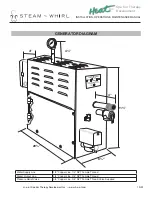
Page 10: ...le Thread Pressure Relief Valve 3 4 Copper Line 3 4 NPT Female Thread Valve Supplied 4 20 8 21 4 4 STEAM WHIRL STEAM BATH GENERATOR MODEL NO SER NO VOLTS PH AMPS KW MFG BY STEAM WHIRL PRODUCTS LAS VEG...

Page 11: ...2 L 2 L 1 Coil Contactor 208 240V Timer 208 240 Load 4 5 3 2 T 1 Fuses TIMER COM NC NO T 1 T 2 STEAM WHIRL L 2 L 1 Plate Screw Ground Blow Down Valve Ground Ground Plate Screw Ground Plate Screw Prob...

Page 12: ...obe 208 240V Timer 208 240 Load 4 5 3 2 T 1 Fuses TIMER COM NC NO T 1 T 2 STEAM WHIRL Plate Screw Ground Blow Down Valve Ground Ground Plate Screw Ground Plate Screw Classic Mechanical Timer Ground He...

Page 13: ...3 Probe 208 240V Timer 208 240 Load 4 5 3 2 T 1 Fuses TIMER COM NC NO T 1 T 2 STEAM WHIRL Plate Screw Ground Blow Down Valve Ground Ground Plate Screw Ground Plate Screw Classic Mechanical Timer Grou...

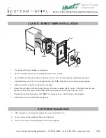
Page 14: ...tor 4 Insert wired timer into a 2 1 2 min deep wall box with TOP indicated on front cover in proper position 5 Fasten to wall box using the two 2 screws supplied 6 Fasten the wall plate to the timer u...

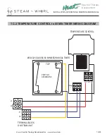
Page 15: ...ER WIRING DIAGRAM COM Stage 1 240 120 C NC NO L1 L2 T1 T2 C C NO NC 1 1 2 2 TOP PART NO C9360NONC 90 4325 CLASSIC 60 MIN MECHANICAL TIMER TEMPERATURE CONTROL TERMINAL BLOCK ON STEAM UNIT Spa Kur Thera...

Page 16: ...CK WIRING DIAGRAM COM Stage 1 240 120 C NC NO 1 2 3 4 5 TIMER COM NO NC T L1 L2 T1 T2 4320 TIMER 24HR 7DAY 208 240V TIMER 208 240V LOAD TERMIAL BLOCK ON STEAM UNIT TEMPERATURE CONTROL Spa Kur Therapy...

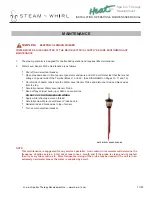
Page 17: ...ly unscrew Water Level Sensor Probe Sand off any calcium build up or debris on sensor tips DO NOT CUT OR TRIM SENSOR WIRES Apply white teflon tape around thread Carefully screw Water Level Sensor Prob...

Page 18: ...______________________________________________ ____________________________________________________________________________ ____________________________________________________________________________...

Page 19: ...and the seller 11 Shipping costs to or from warranty service facility unless required by applicable law 12 Repair or replacement of any installation materials including but not limited to tiles marble...

Page 20: ...Heat Spa Kur Therapy Development Inc www h e a t com DrB h e a t com...

Reviews: