background image

HEAVY COMMERCIAL

STEAMBATH GENERATOR

OWNERS MANUAL

Models HC-9 Thru HC-18

3/98

Pub. No. 400- G

Summary of Contents for HC-10

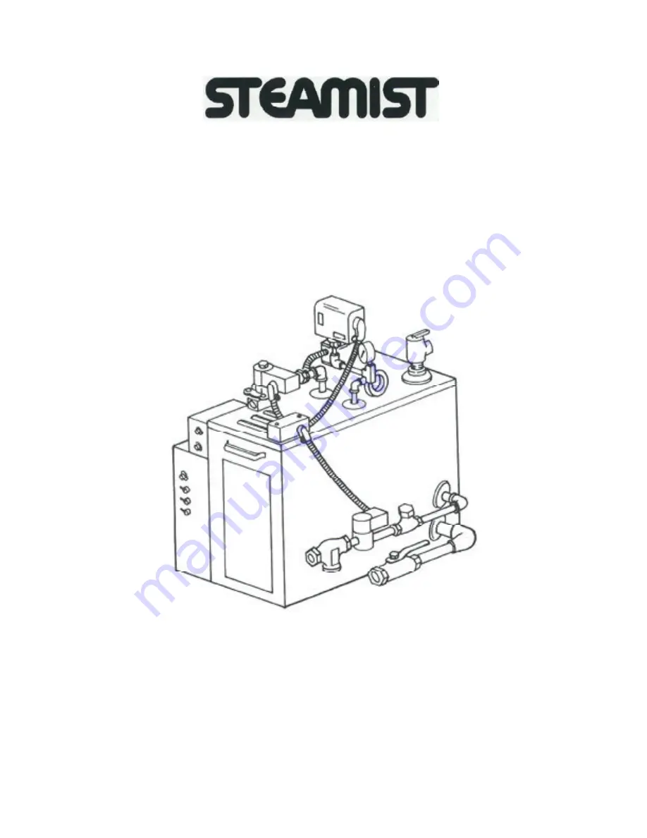
Page 1: ...HEAVY COMMERCIAL STEAMBATH GENERATOR OWNERS MANUAL Models HC 9 Thru HC 18 3 98 Pub No 400 G ...

Page 2: ...Auto Blowdown and Automatic ON OFF Time Clock 8 V Steam Generator Operation 8 VI Steam Generator Maintenance 8 A Manual Blowdown 8 B Periodic Inspection 8 LIST OF ILLUSTRATIONS 1 Dimensional Drawing for Heavy Commercial Steam generator HC 9 thru HC 18 1 2 Typical Steam generator Installation 3 3 ST 200C Temperature Sensor Installation 4 4 ST 200C Temperature Control Installation 5 5 System Control...

Page 3: ...r your steamroom 1 2 3 the steamhead Insulate the steam pipe The serial number plate should be vis ible Refer to Figure 2 for Installation drawing Do not Install outdoors or an area where parts may freeze or corode Also do not install near combustible materials i e paints thinners chlorine etc The steamroom must be completely sealed on all sides top and bottom Floor walls and ceiling should be com...

Page 4: ...nect the steam line from the preViously roughed in location to the steam solenoid valve on the generator marked steam out let See Figure 1 1 2 3 4 In the steamroom place the center of the escutcheon onto the steam pipe and Screw the stearnhead into place Care must be taken not to Scratch the stearnhead or es cutcheon with a wrench Be Sure the steam slot in the stearnhead is facing down After the p...

Page 5: ...TALLATION Replace cover and secure screws removed in step 1 6 NOTE Steam Generator will not operate without water 3 If connections are made properly the indi cator lamp will illuminate when the 7 generator is heating ...

Page 6: ...e INSIDE the steamroom WARNING All electrical power to the steam gen erator MUST be turned OFF before proceeding with installation B CP 1 Control Package Rough in The 3 wire cable for Temperature Control Panel to be used during installation of the ST200C Solid State Temperature Control System is low voltage 18 or 22 AWG wire recommended Every attempt should be made to match the color wire of the T...

Page 7: ...instructions 2 CP 1 System Control Package Installation Temperature Sensor Probe for installation inside the steamroom C 1 Locate the 2 wire cable described in the Rough in section a Keeping the 5 8 inch hole centered drill two 1 4 inch holes 2 inches apart Insert 2 No 8 plastic anchors into drilled holes b c Follow Figure 3 Temperature Control Panel for installation out side the steamroom 2 Attac...

Page 8: ...o the control module Attach wires as shown in the blowup Figure 5 Check that all connections are made b c d in accordance with Wiring Diagram See Figure 7 e Replace control module cover D Steam Solenoid Valve There is no installation required for the steam solenoid valve it is factory installed and wired E Operation The temperature of the steambath is regu lated automatically by the ST 200CTempera...

Page 9: ...PORTANT To check the function two lights are provided on the exterior of the System Control Module located on the steambath generator The Red Light indi cates there is electrical power to the Temperature Control Module The Green Light indicates the Steam Solenoid Valve is energized If a malfunction should occur in either the incom ing electrical power supply Red Light or the Steam Solenoid Valve G...

Page 10: ... been generated from the boiler and the desired temperature reached in the steamroom the steam solenoid valve will close when controlled by the ST 200C The steamroom is now ready for use Note When the steam solenoid valve closes the red pilot light above the toggle switches will go out only after steam pressure builds to ap proximately 8 to 10 PSI within the boiler The boiler will maintain an 8 to...

Page 11: ... a clear plastic dust cover TECHNICAL DATA Output 1 SPDT relay with dry contacts Switch Rating 16A 277VAC resistive 1 OOOW tungsten 240VAC 50OW 120VAC 1 2 hp 120VAC 1 hp 240VAC 100 hour capacitor back up of memory and display Supply voltages Separate Models 24VAC DC 120VAC 208 240VAC all 50 6OHz refer to product label Shortest switch time 1 minute Ambient Temperature Range 20 F to 140 F 28 C to 60...

Page 12: ......

Page 13: ......

Page 14: ......

Reviews: