®
Note: neutral wire required
06/11
Pub. No. 572-C
- 6 -
Instructions for Installation and Use
Table 3 - Wire and Fuse sizes (S170-3)
Model
SMS-80R-3
SMS-100-3
SMS-125-3
SMS-145-3
Watts
8,000
9,800
12,300
14,400
Amps
22.2
27.3
34.1
40.0
Voltage
208
208
208
208
Phase
3
3
3
3
Breaker to Power Unit
1@30A - #10 AWG copper 90°C
1@35A - #8 AWG Copper 90°C
1@50A - #6 AWG Copper 90°C
1@50A - #6 AWG Copper 90°C
Power Unit to Heater
#10 AWG copper 90°C
#8 AWG Copper 90°C
#6 AWG Copper 90°C
#6 AWG Copper 90°C
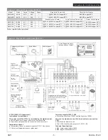
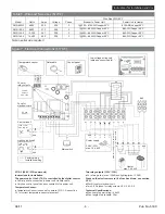
Figure 7 - Electrical Connections (S170-3)
S170-3 (208V / 3PH power unit)
Instructions for Installation
The power unit of the S170-3 is controlled by the digital control.
●
Control panel is connected to power unit via data cable.
●
Only one control panel can be connected to the power unit.
Temperature Sensor:
●
Temperature Sensor is needed to operate S170-3. See section
3.3 for correct temperature sensor placement.
Two relay outputs (120V / 1PH)
●
For driving a fan (max. 100W) and lighting (max. 100W).
Fuses on the electronics card (if a fuse has blown, see section
3.2.2):
●
40mA fuse for electronic unit.
●
Two 2.5 Ah fuses for relay outputs U1, U2, A1, A2.
Technical Specifications:
●
Max. heater power rating: 14.4kW
●
Max. length of data cable: 25 m
Wire Size AWG 90°C
Heater
max. 14.4 kW
G7Z
Power supply
208V / 3PH
max. 14.4 kW
N
L1
L2
L3
N
L
N
L
120V / 1PH
max. 100 W
Slow type
Ceramic
Slow Type
40 mA
T2.5 Ah
A1
A2
L1
N
L2
L3
L1
L2
L3
L1 L2
U1 U2 A1 A2
N
N
A1
A2
L1
L2
L3
GND
GND
GND
GND
GND
Temperature sensor
Data cable
Control panel
Factory wiring
Installation wiring
Lighting (optional)
Fan (optional)
Fuse for
electronic card
Fuse for
relay outputs
Main switch
Blue/Bleu
Yellow/Jaune
White/Blanc
Red/Rouge
120V / 1PH
max. 100 W
Low voltage wiring only
(data and sensor cable)
Minimum 18awg, copper
, 90ºC wire for
A1 and
A2 wires

