®
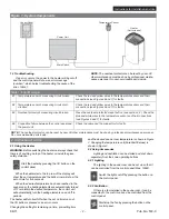
min. 3' 3 3/8"
Models: SMS-60R, SMS-80R and SMS-80R-3
5 7/8“
(150 mm)
Sensor
Capteur
3 15/16”
(100 mm)
3’-7 5/16”
(1100 mm)
D min.
A min.
A min.
A max.
A min.
A max.
D min.
D min.
A min.
3 15/16”
(100 mm)
Sensor
Sensor
Sensor
3 15/16”
(100 mm)
Model
A min. inch (mm)
A max. inch (mm)
D min. inch (mm)
SMS-100 / SMS-100-3
5" (127 mm)
7" (178 mm)
52" (1320 mm)
SMS-125 / SMS-125-3
6" (152 mm)
8" (203 mm)
52" (1320 mm)
SMS-145 / SMS-145-3
6" (152 mm)
8" (203 mm)
52" (1320 mm)
Half the
distance
to the wall
Instructions for Installation and Use
Figure 8
3. Instructions for Installation
Figure 9
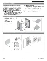
Figure 10 - Sensor's min. distance from an air vent
06/11
Pub. No. 572-C
- 7 -
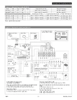
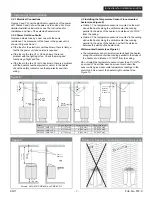
3.2.1 Electrical Connections
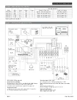
Figures 6 and 7 show the electrical connections of the power
unit. Tables 2 and 3 show the wire and fuse sizes. For more
detailed installation instructions see The Instructions for
Installation and Use of the selected heater model.
3.2.2 Power Unit Fuse Faults
Replace a blown fuse by a new one with the same
resistance. The placement of the fuses in the power unit is
shown in Figures 6 and 7.
●
If the fuse for the electronic unit has blown, there is likely a
fault in the power unit and service is required.
●
If the fuse in the line U1 or U2 has blown, there is a
problem with the lighting or fan. Check the wiring and
functioning of light and fan.
●
If the fuse in the line A1 or A2 has blown, there is a problem
with the heater's overheat protector circuit. In the heater,
check the safety contactor, overheat protector and their
wiring.
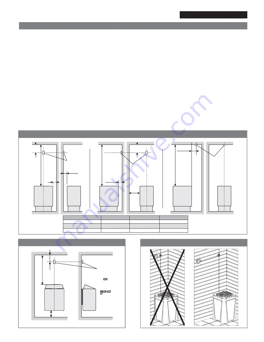
3.3 Installing the Temperature Sensor Floor-mounted
heaters (see Figure 8)
●
Option 1: The temperature sensor is mounted on the wall
above the heater, along the vertical center line running
parallel to the sides of the heater, at a distance of 3 15/16"
from the ceiling.
●
Option 2: The temperature sensor is mounted to the ceiling
above the heater, along the vertical center line running
parallel to the sides of the heater, and half the distance
between the wall and the heater side.
Wall-mounted heaters (see Figure 9)
●
The temperature sensor is wall-mounted above the heater,
along the vertical center line running parallel to the sides of
the heater, at a distance of 3 15/16" from the ceiling.
Do not install the temperature sensor closer than 3'-3 3/8" to
an air vent. The air flow near an air vent cools down the
sensor which gives inaccurate temperature readings to the
control unit. As a result, the heater might overheat. See
Figure 10.

