®
Spring-Set Disc Brakes
P/N 8-078-927-07
effective 5/15/97
Installation and Service Instructions for
87,700 Series Double C-Face Coupler Brake
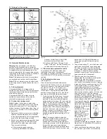
Figure 1
Important
Please read these instructions carefully before
installing, operating, or servicing your Stearns
brake. Failure to comply with these instructions
could cause injury to personnel and/or damage
to property if the brake is installed or operated
incorrectly. For definition of limited warranty/
liability, contact Rexnord Industries, Inc., Stearns
Division, 5150 S. International Dr., Cudahy, WI
53110, (414) 272-1100.
Caution
1. Installation and servicing must be made in
compliance with all local safety codes
including Occupational Safety and Health
Act (OSHA). All wiring and electrical
connections must comply with the National
Electric Code (NEC) and local electric codes
in effect.
2. Do not install the brake in atmospheres
containing explosive gases or dusts.
3. To prevent an electrical hazard, disconnect
power source before working on the brake. If
power disconnect point is out of sight, lock
disconnect in the
off
position and tag to
prevent accidental application of power.
4. Make certain power source conforms to the
requirements specified on the brake
nameplate.
5. Be careful when touching the exterior of an
operating brake. Allow sufficient time for
brake to cool before disassembly. Surfaces
may be hot enough to be painful or cause
injury.
6. Do not operate brake with housing removed.
All moving parts should be guarded.
7. Installation and servicing should be
performed only by qualified personnel
familiar with the construction and operation
of the brake.
8. For proper performance and operation, only
genuine Stearns parts should be used for
repairs and replacements.
9. After usage, the brake interior will contain
burnt and degraded friction material dust.
This dust must be removed before servicing
or adjusting the brake.
DO NOT BLOW OFF DUST using an air
hose. It is important to avoid dispersing dust
into the air or inhaling it, as this may be
dangerous to your health.
a) Wear a filtered mask or a respirator while
removing dust from the inside of a brake.
b) Use a vacuum cleaner or a soft brush to
remove dust from the brake. When
brushing, avoid causing the dust to
become airborne. Collect the dust in a
container, such as a bag, which can be
sealed off.
General Description
The 87,700 Series coupler is a spring-set,
electrically released, self adjusting brake. The
double C-face allows the brake to directly
couple a C-face motor to a C-face gear
reducer. Or, for in-line application, the brake
can be mounted directly to a foot mounted
C-face motor, using the bearing mounted
output shaft as an in-line drive shaft.
Note: Coupler brake is designed for in-line
applications only. Do not apply overhung or
side load to brake output shaft.
Operating Principle
The 87,700 Series brake utilizes one, two or
three rotating friction discs driven by a hub
which is mounted on the motor shaft. The
solenoid air gap is factory set, and normally
requires no resetting even when changing
friction discs. A wrap spring clutch permits the
solenoid air gap to be adjusted automatically to
compensate for friction disc wear or normal
expansion.
When brake is wired into motor circuit, starting
the motor will energize the solenoid and
compress the pressure spring. This action
removes the force against the disc pack
components and allows the friction discs to
rotate freely. De-energizing the motor de-
energizes the solenoid and restores pressure
spring force against the disc pack, thereby
stopping and holding the load.
When the motor is
off
and the load is to be
moved without energizing the motor, the
manual release lever should be used. This
removes the holding torque from the motor
shaft, allowing it to be rotated by hand,
however drag may be noted. The brake will
remain in the manual release position until the
release lever is returned manually to their
set
position or until the brake is re-energized
electrically and the release lever or rod returns
to its
set
position automatically.
Note: The motor should not be run with the
brake in the manual release position to avoid
overheating of friction disc(s).
I. Installation Procedure
Note 1: Check face of motor to which brake is
to be mounted, to be sure NEMA dimensions
of 0.004” T.I.R. on concentricity and face run
out are met. Shaft run out is to be within 0.002”
T.I.R. Maximum shaft end float is 0.020”. Use
standard length NEMA shaft.
Note 2: The effectiveness of the dust-tight
waterproof brake enclosure depends on a fully
enclosed motor C-face as the brake face is not
sealed.
A. Remove hub (16) from brake assembly.
With key (not furnished) in place on motor
shaft, slide hub (square, or splined, end
first) onto shaft to 1” (± 1/32”) of standard
24 tooth
4.24 diameter
16 tooth
3.12 diameter
Splined Configurations


