background image


12


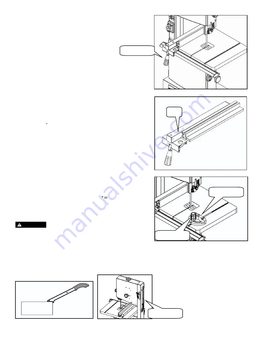
  Clamping the rip fence. 

 Place rip fence on the guide rail. 

 Move the fence to a needed position. The scale 

indicates distance from saw blade to the fence. 

 Tighten the lock lever to clamp the rip fence.  


Fence height can be lowered when cutting thin 
materials. 

Loosen the two knobs (G). (Refer to diagram on previous page). 

Slide the fence out from fence support. 

Rotate fence 90  as shown in the picture on the right.

Insert the lock screw into the other groove of the fence.


Retighten the two knobs (G). 


The fence can be adjusted parallel to the side of the 


blade by loosening the two socket bolts (H).


Using miter gauge.     

The miter gauge is inserted into the table slot from the 
table front edge. 

For miter cuts, the miter gauge can be turned 60
both directions. 

To set a miter angle, loosen the lock handle by turning it 
counter-clockwise. 


Using push stick     

The push stick serves as an extension of the hand and protects against accidental contact with the saw blade.


The push stick must be used if the distance between the bandsaw blade and a rip fence is less than 4” / 150mm.


When the push stick is not use, it can be stored on the hook provided on the bandsaw frame. 

Replace push stick if damaged. 


Lock lever 

Miter gauge 

Lock handle 

Push stick 

‡


‡


‡


‡


‡


‡


‡


‡


‡


‡


‡


‡


‡


‡


‡


When cutting with miter gauge, the lock handle 


WARNING:

must be firmly tightened.

Summary of Contents for 50110

Page 1: ...User Manual Read and understand this manual before using machine 10 2 SPEED BANDSAW STEEL CITY TOOL WORKS VER 10 13 Model Number 50110 ...

Page 2: ...2 TABLE OF CONTENTS Product Specifications 3 Safety 4 Accessories and Attachments 5 Carton Contents 6 Installation 7 Adjustment 8 Operations Maintenance 14 11 ...

Page 3: ... ATTENTION MODEL MOTOR POWER BLADE SIZE THROAT WIDTH CUTTING CAPACITY CUTTING SPEED BLADE RANGE TABLE SIZE CARTON SIZE WEIGHT GW NW 50110 1 2 HP 72 1826mm length x 3 8 6 12 5mm width 9 5 245mm 6 150mm 15 min 400m min LOW HIGH 31 min 800m min 1 8 1 2 14 360mm x 12 5 320mm 40 x 18 x 15 1015 x 450 x 380mm 86lb 39kg 82lb 37kg 3 ...

Page 4: ...14 The use of accessories and attachments not recommended by SCTW may cause damage to the machine or injury to the user Use the proper extension cord 15 Make sure your extension cord is in good condition When using an extension cord be sure to use one heavy enough to carry the current your product will draw An undersized cord will cause a drop in line voltage resulting in loss of power and overhea...

Page 5: ... in line voltage resulting in loss of power and overheating BE SURE YOUR EXTENSION CORD IS PROPERLY WIRED and in good condition Always replace a damaged extension cord or have it repaired by a qualified person before using it Protect your extension cords from sharp objects excessive heat and damp or wet areas Check with a qualified electrician if you do not understand grounding instructions or if ...

Page 6: ... CARTON CONTENTS UNPACKING AND CHECKING CONTENTS Carefully unpack the bandsaw and all its parts Compare against the illustration drawing below WARNING To avoid injury from unexpected starting do not plug the power cord into a power source receptacle during unpacking and assembly This cord must remain unplugged whenever you are assembling or adjusting the bandsaw If any part is missing or damaged d...

Page 7: ...12 carriage bolts 6mm flat washers and M6 hex nuts DO NOT TIGHTEN THE NUT Stand the bandsaw on a level ground then tighten all bolts and nuts 2 Assembling table After attaching the stand assemble the table to bandsaw by using M6x10 bolts Make sure the saw blade is in the center of the table s insert slot 3 Installing the guide rail Secure the guide rail with four knobs to the table 5 Set rip fence...

Page 8: ... blade Turn setting knob clockwise or counterclockwise until the saw blade tracks are centered on the rubber tire After adjusting re tighten the tracking lock knob and close the cover 3 Adjusting the blade tension Raise upper blade guide fully Taking the blade width into consideration turn the knob to adjust tension Check tension by pushing with a finger halfway between table and upper guide again...

Page 9: ...lade guide needs to be adjusted prior to every cutting operation to accommodate the height of workpiece the upper blade guide should be set approximately 1 8 3mm above the workpiece 5 Align the lower blade guide Loosen the socket bolt D and move the entire lower blade guide Adjust the guide bearing to a position of 3 64 1mm or 5 64 2mm from the bottom of the blade Re tighten the socket bolt D Loos...

Page 10: ...riginal position Close the upper and lower covers Next align the saw blade adjust the blade tension and adjust the upper blade guide and lower blade guide Adjusting belt tension If necessary adjust the motor position to adjust the belt tension Loosen the motor locking bolt and turn the motor counter clockwise to reduce the driving belt tension turn the motor clockwise to increase the driving belt ...

Page 11: ... the user Take care to avoid a risk of a kickback 11 To reduce the risk of personal injury the following safety recommendations should be observed when operating the saw OPERATIONS WARNING Switch action To start the tool turn ON the main switch To stop the tool turn OFF the main switch Using rip fence The rip fence can be used on both sides of the blade When the rip fence is moved from one side of...

Page 12: ... by loosening the two socket bolts H Using miter gauge The miter gauge is inserted into the table slot from the table front edge For miter cuts the miter gauge can be turned 60 both directions To set a miter angle loosen the lock handle by turning it counter clockwise Using push stick The push stick serves as an extension of the hand and protects against accidental contact with the saw blade The p...

Page 13: ...ediately afterwards Connecting to dust collector The bandsaw provides a dust port It should be connected with the dust collector when sawing wood If you do not have a dedicated bandsaw extraction there is another way to get rid of the saw dust Most debris except usual dust drifts would fall through a grate into the dust drawer It can be easily pulled out and cleaned Dust port Dust drawer ...

Page 14: ...and moving parts inside the bandsaw 3 LUBRICATION To keep the bandsaw in top running condition and to assure maximum service life oil or grease the moving parts and rotating parts from time to time To reduce the emitted noise always be sure that the blade is sharp and clean 4 KEEP IN STORAGE The bandsaw should be kept in a dry clean and non corrosive environment Always be sure the tool is switched...

Page 15: ...STEEL CITY TOOL WORKS www steelcitytoolworks com 1 877 SC4 TOOL 1 877 724 8665 ...

Page 16: ...NOTES www steelcitytoolworks com Steel City Tool Works LLC Bolingbrook IL USA 60440 Tech Service 1 877 724 8665 ...

Reviews: