21
ADJUSTMENTS
The Sanding Drum is aligned parallel with the table and
completely adjusted at the factory during assembly.
However, due to stresses that occur to the unit during
shipping. It is recommended that you adjust or align
your sander using the following procedures to return it
to optimal working conditions. Do not attempt to use
the sander until you have performed all of the adjust-
ments in this section.
SANDING DRUM ALIGNMENT
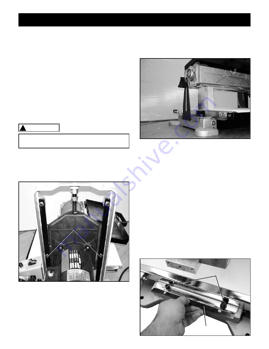
The tightness of the Elevation Tension Adjustment
Screws needs to be adjusted to allow for smooth height
adjustments while still ensuring a tight enough fit as to
limit deflection of the drum. Too tight a fit will result in
difficulty in making height adjustments. Too loose a fit
will cause the drum to deflect excessively. To adjust:
1.
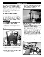
Loosen the locknuts (not shown) on the opposite
end of the Elevation Tension Adjustment Screws
(A).
SEE FIG 5.
MAKE CERTAIN THAT THE SANDER IS DISCON-
NECTED FROM THE POWER SOURCE.
WARNING
!
Fig. 5
A
2.
Loosen or tighten each screw as required. Make
adjustment in 1/4 turn increments until the desired
fit is achieved.
3.
Retighten the locknuts loosened in step 1 to secure
the tension screws in position.
4.
Place a block of wood at the left side of the sander
between the drum and the conveyor belt. We will
call this Measurement A.
SEE FIG. 6.
Fig. 6
NOTE:
The abrasive strip must
NOT
be on the drum
when performing this step.
5.
Crank the handwheel counterclockwise to lower the
drum until it just touches the block of wood
6.
Using a feeler gauge, check and see the clearance
between the block of wood and the drum.
7.
Without raising or lowering the drum, slide the block
of wood over to the right side of the sander and,
again, using a feeler gauge, check the clearance
between the drum and the block of wood. This is
Measurement B. The difference between the meas-
urement A and Measurement B should be .010 or
less. If this is the case, no further adjustment is
necessary. Otherwise,
If Measurement A is greater than Measurement B by
.020 or less:
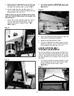
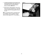
1.
Loosen the two outboard conveyor table mounting
bolts (A)
SEE FIG 7.
Fig. 7
B
A
Summary of Contents for 55210
Page 27: ...27 N NOTES N ...
Page 28: ...28 PARTS ...
Page 30: ...30 ...
Page 32: ...32 ...
Page 36: ......

