22
2.
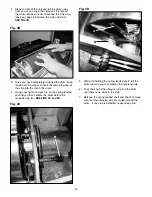
Slide one(or both, depending on how much the two
measurements are off) of the .010 shims (B) under
the edge of the conveyor belt as shown in
FIG 7.
3.
Recheck Measurement A and Measurement B
again. Confirm that the difference between the two
Measurements is less than .010.
If Measurement A is greater that Measurement B by
more than .020 OR If Measurement B is greater than
Measurement A:
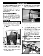
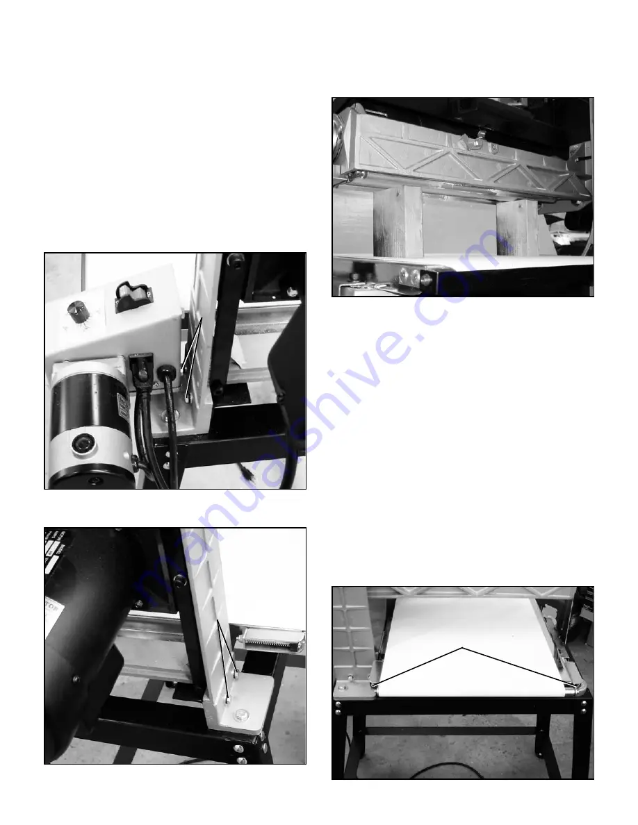
1. Loosen the two front adjustment bolts (A) and the
two rear adjustment bolts (B) slightly. This will
allow the entire drum assembly to pivot.
SEE
FIGS. 8 and 9.
Fig. 8
Fig. 9
A
B
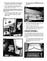
2.
Using two wood blocks of
IDENTICAL
height, place
one at Measurement A and one at Measurement B.
SEE FIG. 10.
Fig. 10
MEASUREMENT
A
MEASUREMENT
B
3.
Crank the handwheel counterclockwise to lower the
drum until it touches both wood blocks.
4.
Retighten the bolts loosened in step 1.
5.
Using one woodblock and a feeler gauge, recheck
both Measurements A and B. Confirm that the dif-
ference between the two is less than .010
CONVEYOR FEED BELT
TRACKING ADJUSTMENT
Occasional adjustment of the conveyor feed belt track-
ing may be required due to belt stretching, normal wear
and tear, and improper tensioning. Ideally, the conveyor
feed belt should track in the center of the conveyor belt
feed table
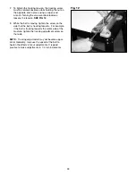
1.
The conveyor belt feed tracking adjustment screws
(A) are located at the rear of the machine on both
the left and right side of the drum sander.
SEE FIG 11.
Fig. 11
A
Summary of Contents for 55210
Page 27: ...27 N NOTES N ...
Page 28: ...28 PARTS ...
Page 30: ...30 ...
Page 32: ...32 ...
Page 36: ......

