ST1001 6" Jointer
-15-
Once assembly is complete and you have read the
Safety
section on
Page 4
, test run the machine
before continuing with the setup.
If, during the test run, you cannot easily locate the
source of an unusual noise or vibration, stop using
the machine immediately, then contact our Technical
Support Staff for further assistance.
Test Run
Wear safety glasses during
the entire test run process.
Failure to comply may
result in serious personal
injury.
To test run the machine:
1.
Make sure you have performed the
Setting
Outfeed Table Height
instructions on
Page 14
.
2.
Connect the machine to the power source.
3.
Turn the jointer
ON
to allow it to reach full
speed, then turn the jointer
OFF
.
—The jointer should run smoothly with little or
no vibration or rubbing noises. Disconnect
power before troubleshooting any problems.
4.
Remove the switch safety key.
5.
Try to turn the jointer
ON
with the key
removed.
— If the jointer starts with the key removed, dis-
connect power immediately and call Technical
Support.
— If the jointer does not start with the key
removed then it is operating properly.
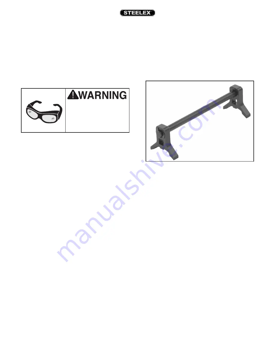
Knife Setting Jig
Figure 21.
Knife setting jig assembly.
Components and Hardware Needed:
Qty
Knife Setting Jig Rod ........................................................... 1
Knife Setting Jig Foot .......................................................... 2
E-Clip ......................................................................................... 4
Assemble the knife setting jig as shown in Figure
21.
For your convenience, the adjustments listed below
have been performed at the factory and no further
setup is required to operate your machine.
However, because of the many variables involved
with shipping, we recommend that you at least verify
the following adjustments to ensure the best pos-
sible results from your new machine.
Step-by-step instructions for these adjustments can
be found in the
SERVICE
section.
Factory adjustments we recommend you verify:
1.
Knife Height Settings (
Page 26
).
2.
Depth Scale Calibration (
Page 29
).
3.
Fence Stop Accuracy (
Page 30
).
Recommended
Adjustments
Summary of Contents for ST1001
Page 2: ......
Page 36: ...34 ST1001 6 Jointer ST1001 Wiring Diagram...
Page 37: ...ST1001 6 Jointer 35 Jointer Breakdown...
Page 39: ...ST1001 6 Jointer 37 Fence Breakdown...
Page 44: ......
Page 47: ......
Page 48: ......

