ST1001 6" Jointer
-27-
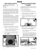
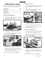
Figure 40.
Cutterhead profile diagram.
������
������
�����
��������
���
����
�����
�������
The Model ST1001 comes with both jack screws and
springs inside the cutterhead to provide two options
for adjusting the knives (see
Figure 40
).
Note:
Only
one of these options is needed to set the knives—see
Step 7 on Page 28
for clarification.
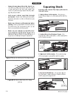
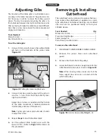
Figure 39.
Using knife setting jig to set knife height.
Knife Setting Jig Method:
Both tables are lowered to
fit the jig on the cutterhead, as shown in
Figure 39
,
and the knife heights are set to just touch the middle
pad of the jig.
The knife setting jig makes it easy to ensure that the
knives project out of the cutterhead evenly. After
using the knife setting jig to set the knives, you have
to re-adjust the outfeed table height to ensure that it
is even with the knives at their highest point of rota-
tion. If you use the positive stops on the tables, reset
them before operation.
Adjusting/Replacing
Knives
Setting the knives correctly is crucial to the proper
operation of the jointer and is very important in
keeping the knives sharp. If one knife is higher than
the others, it will do the majority of the work, and
thus, dull much faster than the others.
There are two options for setting the knives—the
straightedge method and the knife setting jig meth-
od. Each option has advantages and disadvantages
and the correct one for you will become a matter of
personal preference.
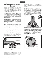
Straightedge Method:
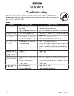
A high quality straightedge
is held flat against the outfeed table and the knife
heights are set to the bottom of the straightedge, as
shown in
Figure 37
.
When using a straightedge to set the knives, you are
assured that the knives are even with the outfeed
table in their highest point of rotation—even if the
cutterhead is not parallel with the outfeed table.
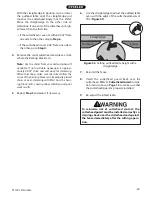
To use the straightedge method, disconnect power
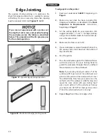
and place the straightedge on the outfeed table
so it hangs over the cutterhead. Lower the outfeed
table until the straightedge is 0.062" (1⁄16") above
the cutterhead body, as determined by using a feeler
gauge or combination of feeler gauges between the
bottom of the straightedge and the cutterhead body
(see
Figure 38
). Tighten the outfeed table lock.
������������
�������������
��������
�
�
��
��
������������
Figure 38.
Using feeler gauge to set outfeed table
height.
Now, set the knife heights to the new outfeed table
height. (As long as the outfeed table remains locked,
that part of the procedure will not have to be repeat-
ed the next time you replace or adjust the knives.)
Summary of Contents for ST1001
Page 2: ......
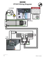
Page 36: ...34 ST1001 6 Jointer ST1001 Wiring Diagram...
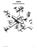
Page 37: ...ST1001 6 Jointer 35 Jointer Breakdown...
Page 39: ...ST1001 6 Jointer 37 Fence Breakdown...
Page 44: ......
Page 47: ......
Page 48: ......


