background image

-38-

ST1001 6" Jointer

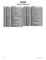
Fence Parts List

REF

PART #

DESCRIPTION

REF

PART #

DESCRIPTION

201

XST1001201

FENCE

222

XST1001222

SHAFT

202

XST1001202

CAUTION LABEL

223

XPSB13M

CAP SCREW M8-1.25 X 30

203

XST1001141

RIVET 2 X 4MM

224

XST1001224

BALL KNOB

204

XST1001204

STUD

225

XST1001225

COMPRESSION SPRING

205

XST1001205

BALL KNOB

226

XST1001226

INDEX PIN

206

XST1001206

SPECIAL SCREW

227

XPRP42M

ROLL PIN 3 X 20MM

207

XPW01M

FLAT WASHER 8MM

228

XST1001228

INDEX COLLAR

208

XST1001208

WAVY WASHER 8MM

229

XST1001229

FENCE LOCK HANDLE M8-1.25

209

XST1001209

LEAF GUARD

230

XPW01M

FLAT WASHER 8MM

210

XST1001210

FENCE TILT LOCK HANDLE M10-1.5

231

XST1001231

COVER

211

XST1001211

BLOCK

232

XPS68M

PHLP HD SCR M6-1 X 10

212

XST1001212

BLOCK

233

XST1001233

COVER

213

XST1001213

SUPPORT

234

XPSB58M

CAP SCREW M8-1.25 X 12

214

XPB29M

HEX BOLT M6-1 X 30

235

XST1001235

GUARD

215

XPSB37M

CAP SCREW M6-1 X 50

237

XPW01M

FLAT WASHER 8MM

216

XPN01M

HEX NUT M6-1

238

XPSB155M

CAP SCREW M8-1.25 X 14

217

XST1001217

COLLAR

239

XST1001239

BAR

218

XPSS14M

SET SCREW M8-1.25 X 12

240

XST1001240

SUPPORT

219

XST1001219

SHAFT

241

XPSB60M

CAP SCREW M8-1.25 X 55

220

XPSB31M

CAP SCREW M8-1.25 X 25

242

XPRP39M

ROLL PIN 4 X 20MM

221

XST1001221

INDEX COLLAR

Summary of Contents for ST1001

Page 1: ...port shopfox biz COPYRIGHT SEPTEMBER 2006 BY WOODSTOCK INTERNATIONAL INC WARNING NO PORTION OF THIS MANUAL MAY BE REPRODUCED IN ANY SHAPE OR FORM WITHOUT THE WRITTEN APPROVAL OF WOODSTOCK INTERNATIONA...

Page 2: ......

Page 3: ...S 16 Operation Safety 16 Basic Controls 16 Stock Inspection and Requirements 17 Squaring Stock 18 Surface Planing 19 Edge Jointing 20 Bevel Cutting 21 Rabbet Cutting 22 MAINTENANCE 23 Schedule 23 Clea...

Page 4: ...s Cutting Capacities Maximum Cutting Width 6 Maximum Cutting Depth per pass 1 8 Minimum Workpiece Length 10 Minimum Workpiece Height 1 Minimum Workpiece Thickness 1 2 Cutterhead Information Cutterhead...

Page 5: ...utterhead Guard D Infeed Table E Infeed Table Adjustment Lever F Cutting Depth Scale G ON OFF Switch w Removable Key H 4 Dust Port I Spring Knob J Outfeed Table Adjustment Knob K Fence Tilt Lever L Fe...

Page 6: ...is risk by wearing safety glasses Everyday eyeglass es only have impact resistant lenses they are NOT safety glasses Zero Risk Does Not Exist As with any human activity zero risk from using machinery...

Page 7: ...FORE doing any work on machine including chang ing blades or other tooling Safety Instructions 14 JOINTER KICKBACK As with all jointers this machinemay kickback theworkpiece which means throwing it fr...

Page 8: ...nnect your machine to a shared circuit consult a qualified electrician 110V Circuit 20 Amps Plug Receptacle Type Included 110V Plug Type NEMA 5 15 This machine must have a ground prong in the plug to...

Page 9: ...his machine presents serious injury hazards to untrained users Read through this entire manual to become familiar with the controls and opera tions before starting the machine Unpacking SETUP Thefollo...

Page 10: ...r to Stand 3 Key Motor Pulley 1 Carriage Bolts 5 16 18 x 13 16 Motor 4 Flat Washers 5 16 Motor 4 Lock Washers 5 16 Motor 4 Hex Nuts 5 16 18 Motor 4 Phillips Head Screws M6 1 x 10 Belt Guard 4 Lock Was...

Page 11: ...a solvent cleaner or citrus based degreaser To clean thoroughly some parts may need to be removed For optimum performance from your machine make sure you clean all moving parts or sliding contact sur...

Page 12: ...elf while unpacking and mounting this component get assis tance Components and Hardware Needed Qty Assembled Stand 1 Jointer Unit 1 Mounting Bolts 3 Flat Washers 10mm 3 Jointer to Stand To mount the j...

Page 13: ...oard as shown in Figure 8 Motor Figure 9 Installing the motor pulley Figure 8 Jointer on its side for motor installation 4 Place the motor on the motor mount bracket so the motor shaft faces the rear...

Page 14: ...ence Mounting Location 2 Place the fence cover over the shaft at the rear of the fence and attach it to the fence with the lock handle cap screw and flat washers shown in Figure 14 Figure 14 Fence cov...

Page 15: ...the fence face as shown in Figure 17 Cutterhead Guard Figure 17 Cutterhead guard installed and in the correct resting position Components and Hardware Needed Qty Fence Adjustment Lever 1 Infeed Table...

Page 16: ...nto the dust chute motor mount If you are not installing the dust port secure the dust chute with the wing screws Otherwise proceed to the next step 2 Place the dust port over the bottom of the dust c...

Page 17: ...e the switch safety key 5 Try to turn the jointer ON with the key removed If the jointer starts with the key removed dis connect power immediately and callTechnical Support If the jointer does not sta...

Page 18: ...s Basic Controls This section covers the basic controls used during routine operations Table Movement To move the infeed table loosen the table lock Figure 22 and move the table with the table lever L...

Page 19: ...eeded Figure 24 Fence lock location Fence Lock Fence Tilting The tilt lock Figure 25 secures the fence at any position in the available range The plunger locks into an indexing ring to easily set the...

Page 20: ...igures 27 28 before edge jointing or surface planing or it may break or kickback during the operation Figure 27 Minimum dimensions for edge jointing 1 2 Min 1 Min 10 Min Figure 28 Minimum dimensions f...

Page 21: ...ocedure will better prepare you for the actual operation Figure 30 Illustration of surface planing results 7 With a push block in each hand press the workpiece against the table and fence with firm pr...

Page 22: ...the surface of the infeed table 6 Start the jointer 7 Press the workpiece against the table and fence with firm pressure Use your trailing hand to guide the workpiece through the cut and feed the wor...

Page 23: ...n the surface of the infeed table 6 Start the jointer 7 With a push block in your leading hand press the workpiece against the table and fence with firm pressure and feed the workpiece over the cutter...

Page 24: ...le and fence with firm pressure and feed the workpiece over the cutterhead Note When your leading hand gets within 4 of the cutterhead lift it up and over the cutterhead and place the push block on th...

Page 25: ...ips sawdust and wipe off the remaining dust with a dry cloth If any resin has built up remove it with a resin dissolving cleaner Cleaning MAINTENANCE Always disconnect power to the machine before perf...

Page 26: ...Motor stalls or shuts off during a cut 1 Motor overloaded during operation 2 Circuit breaker tripped 3 Short circuit in motor or loose connec tions 1 Reduce load on motor take lighter cuts 2 Reset th...

Page 27: ...use clean stock 2 Adjust one of the nicked knives sideways replace knives Page 27 3 Slow down the feed rate 4 Take a smaller depth of cut Always reduce cutting depth when surface planing or working wi...

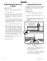
Page 28: ...the V belt 1 DISCONNECT JOINTER FROM POWER SOURCE 2 Remove the V belt cover 3 Loosen the four hex nuts that secure the motor to the motor mount Refer to the motor instal lation instructions on Page 1...

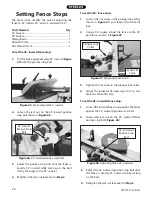
Page 29: ...ork and thus dull much faster than the others There are two options for setting the knives the straightedge method and the knife setting jig meth od Each option has advantages and disadvantages and th...

Page 30: ...ust tight enough to hold the knife in place Repeat on the other side of the cutterhead then repeat Steps 5 7 with the rest of the knives Tools Needed Qty Straightedge 1 Knife Setting Jig Optional 1 He...

Page 31: ...e 44 Depth scale adjusted to 0 position 8 Rotate the cutterhead to the first knife you start ed with Slightly tighten all the gib bolts starting in the middle and working your way to the ends by alter...

Page 32: ...n the 45 outward fence positive stop bolt Figure 48 Figure 47 Adjusting fence to 90 Plunger Lock Collar Fence Tilt Scale Figure 48 Adjusting fence 45 outward 45 Outward Positive Stop Bolt Setting Fenc...

Page 33: ...ghter gibs reduce play but make it harder to adjust the tables 3 Repeat Steps 1 2 with the other table 4 Set the outfeed table height even with the knives at TDC Refer to Page 14 for details on this p...

Page 34: ...e these carefully pull them off and set them aside for later use or keep them with your cutterhead in the event that you reinstall it later Also mark the side of the cutterhead where they were used so...

Page 35: ...other go to Step 4 4 Remove the spiral cutterhead and place a shim where the bearing block rests Note Use the shims from your old cutterhead if available If not available newspaper is approxi mately 0...

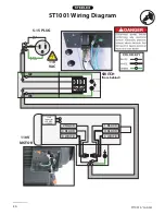
Page 36: ...34 ST1001 6 Jointer ST1001 Wiring Diagram...

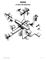
Page 37: ...ST1001 6 Jointer 35 Jointer Breakdown...

Page 38: ...1001119 PLASTIC KNOB 162 XST1001162 BLOCK 120 XPSS02M SET SCREW M6 1 X 6 163 XST1001163 LINK 121 XST1001121 COLLAR 164 XST1001164 SPECIAL BOLT 122 XST1001122 SPACER 165 XPSS20M SET SCREW M8 1 25 X 8 1...

Page 39: ...ST1001 6 Jointer 37 Fence Breakdown...

Page 40: ...OCK HANDLE M8 1 25 209 XST1001209 LEAF GUARD 230 XPW01M FLAT WASHER 8MM 210 XST1001210 FENCE TILT LOCK HANDLE M10 1 5 231 XST1001231 COVER 211 XST1001211 BLOCK 232 XPS68M PHLP HD SCR M6 1 X 10 212 XST...

Page 41: ...16 18 326 XST1001326 LOWER FRONT REAR BRACE 309 XST1001309 WING BOLT M5 8 X 12 327 XST1001327 PLASTIC FOOT 310 XPCB02 CARRIAGE BOLT 5 16 18 X 1 2 328 XPCB02 CARRIAGE BOLT 5 16 18 X 1 2 311 XST1001311...

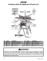
Page 42: ...D MANUAL LABEL 409 XST1001409 STEELEX NAMEPLATE 405 XST1001405 MACHINE ID LABEL 410 XST1001410 STEELEX GRAY TOUCH UP PAINT Safety labels warn about machine hazards and how to prevent serious personal...

Page 43: ...ct resulted from causes not within the scope of Woodstock International Inc s warranty then the original owner must bear the cost of storing and returning the product This is Woodstock International I...

Page 44: ......

Page 45: ...to a friend _____ Yes _____ No 6 What is your age group _____ 20 29 _____30 39 _____ 40 49 _____ 50 59 _____60 69 _____ 70 7 What is your annual household income _____ 20 000 29 000 _____ 30 000 39 00...

Page 46: ...TAPE ALONG EDGES PLEASE DO NOT STAPLE FOLD ALONG DOTTED LINE FOLD ALONG DOTTED LINE WOODSTOCK INTERNATIONAL INC P O BOX 2309 BELLINGHAM WA 98227 2309 Place Stamp Here...

Page 47: ......

Page 48: ......
Reviews: