-22-
ST1006/ST1011 8" Jointer (Mfd. Since 3/16)
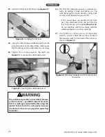
23. Install the tilt lever in the fence (see Figure 20).
Figure 20. Installing the tilt lever.
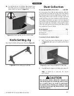
24. Insert the shaft of the cutterhead guard into the
hole at the front of the infeed table, making sure
that the flat part of the shaft faces the set screw.
25. Tighten the set screw against the shaft (see
Figure 21) to secure the cutterhead guard.
Figure 21. Securing the cutterhead guard.
The cutterhead guard is a critical safety feature
on this machine—you MUST install and verify
that it is working as intended before using the
jointer! Failure to do this will greatly increase
the chances of a serious injury when operating
the jointer.
26. Test that the cutterhead guard is working cor-
rectly by pulling it back and letting go. The
cutterhead guard should quickly spring back
over the cutterhead when you do this.
— If the guard does not quickly spring back
over the cutterhead when you perform this
test, then remove it and repeat Steps 24–26.
Do not continue with the assembly until the
cutterhead guard is working correctly.
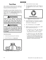
27. Use (2) M10-1.5 x 25 cap screws, (2) 10mm lock
washers, and (2) 10mm flat washers to attach
the pedestal switch to the back of the jointer, as
shown in Figure 22.
Figure 22. Attaching pedestal switch to the back of
the jointer.
x 2

