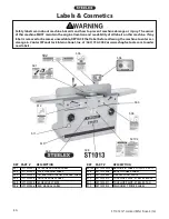
ST1013 12" Jointer (Mfd. Since 3/16)
-43-
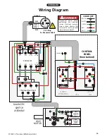
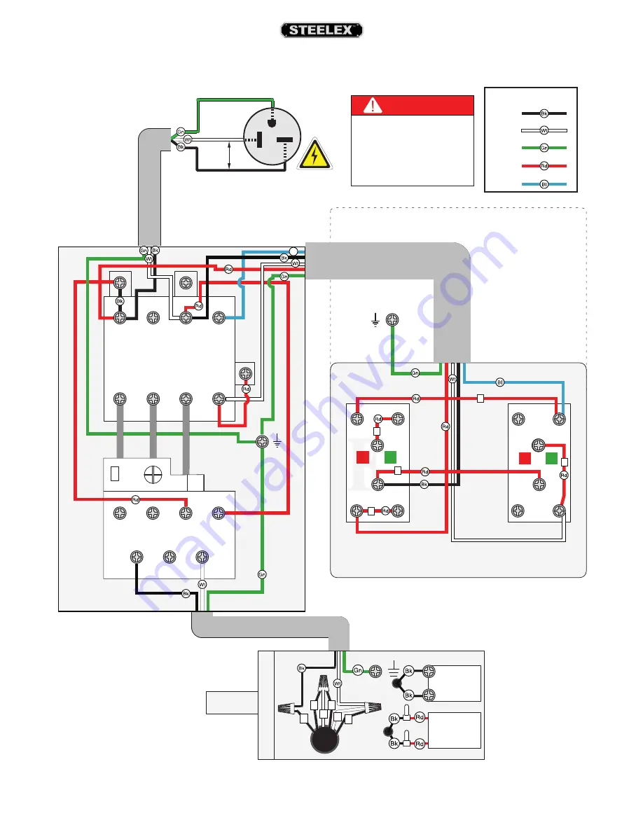
CONTROL
PANEL
(from behind)
MAGNETIC
SWITCH
ASSEMBLY
1L1
3L2
5L3
2T1
4T2
6T3
13no
14no
A2
A1
98
97
96
95
Ground
Hot
Ground
Hot
Bl
Contactor
Thermal Overload
ON
Swit
ch
Top
STOP/R
eset
Swit
ch
2
4
1
3
5
230V
MOTOR
Start
Capacitor
200MFD
250VAC
Run
Capacitor
20MFD
450VAC
1
3
2
4
5 8
Ground
Hot
Hot
Ground
6-20 Plug
(As Recommended)
220
VAC
G
BLACK
WHITE
GREEN
RED
BLUE
COLOR KEY
DANGER
Disconnect power before
performing any electrical
service. Electricity presents
serious shock hazards that
will result in severe personal
injury and even death!
Wiring Diagram

